Page 97 - ITU Journal Future and evolving technologies Volume 2 (2021), Issue 6 – Wireless communication systems in beyond 5G era
P. 97

ITU Journal on Future and Evolving Technologies, Volume 2 (2021), Issue 6


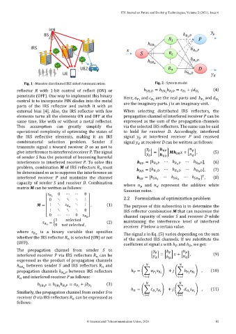
             Fig. 1 –Massive distributed IRS aided communication               Fig. 2 –System model

          reflector  R  with  1-bit  control  of  reflect  (ON)  or       ℎ             = ℎ                   =           +             (4)
                                                                                     ℎ
          penetrate (OFF). One way to implement this binary    Here,     and     are the real parts and      and   
          control is to incorporate PIN diodes into the metal                                                      
          parts  of  the  IRS  reflector  and  switch  it  with  an   are the imaginary parts. j is an imaginary unit.
          external  bias  [4].  Also,  the  IRS  reflector  with  few   When  selecting  distributed  IRS  reflectors,  the
          elements turns all the elements ON and OFF at the    propagation channel of interfered receiver P can be
          same time, like with or without a metal reflector.   expressed as the sum of the propagation channels
          This  assumption  can  greatly  simplify  the        via the selected IRS reflectors. The same can be said
          operational complexity of optimizing the states of   to  hold  for  receiver  D.  Accordingly,  interfered
          the  IRS  reflective  elements,  making  it  an  IRS   signal      at  interfered  receiver  P  and  received
                                                                         
          combinatorial  selection  problem.  Sender  S        signal     at receiver D can be written as follows:
                                                                         
          transmits signal  x toward receiver  D so  as not to                                     
          give interference to interfered receiver P. The signal          [       ] = [       ]         + [       ] ,  (5)
                                                                                              
          of sender S has the potential of becoming harmful                                         
          interference to interfered receiver P. To solve this                 = [ℎ    1     ⋯ ℎ           ⋯ ℎ         ],  (6)
          problem, combination M of IRS reflectors     must               = [ℎ      ⋯ ℎ        ⋯ ℎ           (7)
                                                     
          be determined so as to suppress the interference on                     1                         ],
                                                                                                         
          interfered  receiver  P  and  maximize  the  channel                 = [ℎ      1  ⋯ ℎ          ⋯ ℎ         ] ,  (8)
          capacity of  sender  S  and  receiver  D.  Combination   where      and      represent  the  additive  white
          matrix M can be written as follows:                                     
                                                               Gaussian noise.
                              0   ⋯    ⋯    0
                             1
                           0  ⋱    ⋱   ⋱    ⋮                  2.2  Formulation of optimization problem

                       =     ⋮  ⋱            ⋱  ⋮     ,  (1)   The purpose of this subsection is to determine the
                           ⋮  ⋱    ⋱   ⋱    0                  IRS reflector combination    that can maximize the
                        [ 0   ⋯   ⋯    0      ]                channel capacity of sender S and receiver D while
                                                 
                             1                    
                          = {                          (2)     maintaining  the  interference  level  of  interfered
                              0                         ,      receiver  P below a certain value.
          where       is  a  binary  variable  that  specifies
                                                               The signal x in Eq. (5) varies depending on the sum
          whether the IRS reflector     is selected (ON) or not   of  the  selected  IRS  channels.  If  we  substitute  the
                                     
          (OFF).                                               coefficient of signal x with ℎ  and ℎ , we get:
                                                                                                  
                                                                                           
          The  propagation  channel  from  sender  S  to                             ℎ            
          interfered  receiver  P  via  IRS  reflectors     can  be          [       ] = [ ℎ    ]    + [       ] ,  (9)
                                                   
          expressed as the product of propagation channels                              
          ℎ    between  sender  S  and  IRS  reflectors     and                              
                                                      
          propagation channels ℎ           between IRS reflectors   ℎ = (∑       ) +    (∑       ) ,       (10)


              and interfered receiver P as follows:                         =                =  
             
                               ℎ
                    ℎ             = ℎ                   =    +             (3)               
                                            
                                                                   ℎ = (∑       ) +    (∑       ) ,        (11)
          Similarly, the propagation channel from sender S to                                             
          receiver D via IRS reflectors     can be expressed as             =                =  
                                       
          follows:

                                             © International Telecommunication Union, 2021                    85
   92   93   94   95   96   97   98   99   100   101   102