
Page 74 - ITU Journal Future and evolving technologies Volume 2 (2021), Issue 6 – Wireless communication systems in beyond 5G era
P. 74
ITU Journal on Future and Evolving Technologies, Volume 2 (2021), Issue 6
Δ
Ρ , , , , , slice users (i.e., vehicle) in the V2V‑communication layer
⎧log 1 + , ∀ → ,
2 2 is given as [65]:
⎪
⎪ ∀ ∈ {ℰ ∪ ℳ } 41 + 22.7 log(3) + 20 log ℎ/5 ,
⎪ , , , , , ⎧
⎪ ∀ ∈ ℐ ⎪ d , , ≤ 3
⎪ ⎪
Δ
⎪ log 1 + Ρ , , , , , , ⎪41 + 22.7 log(d , , ) + 20 log ℎ/5 ,
⎪ 2 + Ρ Δ , , , = d , , ≤ d ℎ
2
⎪ , , , , , ⎨
⎪ ∈{ } ⎪ 9.45 + 40 log(d , , ) + 2.7 log ℎ/5
≠
, , , = = ℱ | → ; = | → ⎪ − 17.3 log − 1 − 1 ,
⎨ ⎪ , , ,
⎪ ⎩ d ℎ ≤ d , ,
⎪ Ρ Δ (4)
⎪ log 1 + , ∈ , , , ∈ , , where d , , denotes the distance between a vehicle ∈
⎪ 2 + Ρ Δ engaged in transmission mode and another slice user
2
⎪ ′ ′ ′ , , , , , (i.e., vehicle) , , ∈ ℛ , , . The notations ℎ, , , , , and
⎪ ∈ ∈{ ℱ } denote the carrier frequency in GHz; the effective an‑
⎪ ≠ ′ ≠ ′ tenna height of the vehicles in V2N and V2V communica‑
⎪ ℱ ≠ ℱ tion layers. The distance threshold denoted as d in
⎪ ∀ → , ∀ ∈ ℐ, (4) takes the following form [65]: ℎ
⎩ ∀ , ∈ {ℰ , , ∪ ℳ , , }
(2) 4( )( )ℎ/5
d ℎ = , , , (5)
where Δ , , , denotes the channel gain of the downlink where represents the speed of light. Based on (4), the
between an access point ∈ { , , , } owned by InP spectrum ef iciency of URLLC users in the V2N communi‑
and a user , subscribed to SP ∈ ; Δ , , , is derived cation layer is given as:
from (1). Ρ , , indicates the downlink transmit power of
the access point ∈ { , , , } belonging to an InP ; and Ρ , , Δ , , , | , , , | 2
is the background noise. The double summation in (2) , , , = log 1+ (6)
2
2
2
when → indicates the associated intra‑cluster inter‑ + Ρ , Δ , , | , | 2
ference, where a cluster comprises femtocells in the cov‑ ∈{ }
≠
erage of a picocell, and as such, the set of clusters is such
that = { | ∈ , 1 ≤ ≤ | |}. The small‑scale fading components are captured in (6) by
the notations , , , and , . Note that the small‑scale
3.5.2 Highly mobile slice users fast fading component is independent and identically dis‑
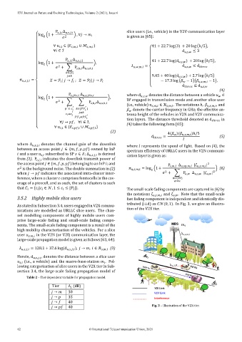
tributed (i.i.d) as (0, 1). In Fig. 3, we give an illustra‑
As stated in Subsection 3.4, users engaged in V2X commu‑
tion of the V2X tier.
nications are modelled as URLLC slice users. The chan‑
nel modelling components of highly mobile users com‑
prise large‑scale fading and small‑scale fading compo‑
MBS
nents. The small‑scale fading component is a result of the
high mobility characterisation of the vehicles. For a slice
user , , in the V2N (or V2I) communication layer, the
large‑scale propagation model is given as follows [63, 64]:
, , , = 128.1 + 37.6 log(d , , , ), → , ∈ ℛ , , (3)
Herein, d , , , , denotes the distance between a slice user
(i.e., a vehicle) and the macro‑base‑station . Fol‑
,
lowing categorisation of slice users in the V2X tier in Sub‑ V2V Tx V2I Rx
section 3.4, the large‑scale fading propagation model of
V2V Rx
Table 2 – Tier dependent variable for propagation model.
Tier Λ (dB) V2I Link
→ 30 V2V Link
→ 35 Interference
→ 40
→ 40 Fig. 3 – Illustration of the V2X‑tier.
62 © International Telecommunication Union, 2021