
Page 86 - ITU Journal Future and evolving technologies – Volume 2 (2021), Issue 2
P. 86
ITU Journal on Future and Evolving Technologies, Volume 2 (2021), Issue 2
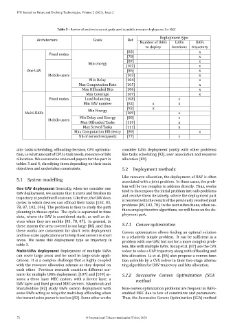
Table 3 – Review of architectures and goals used in mobile resource deployment for MEC
Deployment type
Architecture Goals Ref
Number of UAVs UAVs UAVs
to deploy locations trajectory
[83] x
Fixed nodes
[78] x
[87] x
Min energy
[102] x
One UAV [86] x
Mobile users [103] x
Min Delay [104] x
Max Computation Rate [105] x
Max Of loaded Bits [106] x
Max Coverage [107] x
Fixed nodes Load balancing [108] x
Min UAV number [82] x x
[92] x
Min Energy
Multi‑UAVs [109] x
Min Delay and Energy [88] x
Mobile users
Max Of loaded Tasks [110] x
Max Served Tasks [111] x
Max Computation Ef iciency [89] x
Nb of served resquests [77] x
atic: tasks scheduling, of loading decision, CPU optimiza‑ consider UAVs deployment jointly with other problems
tion, i.e what amount of CPU a task needs, resource or bits like tasks scheduling [92], user association and resource
allocation. We summarize reviewed papers for this part in allocation [89].
tables 3 and 4, classifying them depending on their main
objectives and undertaken constraints. 5.2 Deployment methods
Like resource allocation, the deployment of UAV is often
5.1 System modelling
associated with a joint problem. In these cases, the prob‑
lem will be too complex to address directly. Thus, works
One UAV deployment Generally, when we consider one
tend to decompose the initial problem into sub‑problems
UAV deployment, we assume that it starts and inishes its
and resolve them iteratively, where the deployment part
trajectory at prede ined locations. Like that, the UAV does
is resolved with the results of the previously resolved joint
cycles in which devices can of load their tasks [102, 83,
problems [89, 102, 78]. In the next subsections, when au‑
78, 87, 102, 106]. The problem is then to study the path
thors employ iterative algorithms, we will focus on the de‑
planning in theses cycles. The cycle is separated in time
ployment part.
slots, where the UAV is considered static, as well as de‑
vices when they are mobile [83, 78, 87]. In general, in 5.2.1
these system the area covered is not large [86], and thus Convex optimization
these works are convenient for short term deployment
Convex optimization allows inding an optimal solution
and low‑scale applications or to help ixed servers in short
to a relatively simple problem. It can be icient in a
areas. We name this deployment type as trajectory in
problem with one UAV , but not for a more complex prob‑
table 3.
lem, like with multiple UAVs. Xiong et al. [87] use the CVX
Multi‑UAVs deployment Deployment of multiple UAVs solver to solve a UAV trajectory along with of loading and
can cover large areas and be used in large‑scale appli‑ bits allocation. Li et al. [86] also propose a convex func‑
cations. It is a complex challenge that is highly coupled tion solvable by a CVX solver in their two‑stage alterna-
with the resource allocation scheme as they depend on ting algorithm for UAV trajectory and bits allocation.
each other. Previous research considers different sce‑
5.2.2
nario for multiple UAVs deployment. [107] and [109] as‑ Successive Convex Optimization (SCA
sume a three layer MEC system, with a device layer, a
method
UAV layer and ixed ground MEC servers. Islambouli and
Sharafeddine [82] study UAVs swarm deployment with Non‑convex optimization problems are frequent in UAVs‑
some UAVs acting as relays for multi‑hop of loading when enabled MEC due to lots of constraints and parameters.
the transmission power is too low [82]. Some other works Thus, the Successive Convex Optimization (SCA) method
72 © International Telecommunication Union, 2021