
Page 166 - ITU Journal Future and evolving technologies – Volume 2 (2021), Issue 2
P. 166
ITU Journal on Future and Evolving Technologies, Volume 2 (2021), Issue 2
-0.02
0.9
0.8
-0.01
0.7
0.6
r (m) 0 0.5 Normalized intensity
0.4
0.3
0.01
0.2
0.1
0.02
0 100 200 300
x (m)
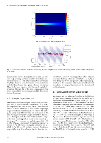
Fig. 13 – Intensity plot of the Gaussian laser beam.
Laser mesh
Target at three
mesh positions
A steering position with L = 3
Fig. 14 – Simultaneous detection, localization, and tracking of a target using three laser mesh at each steering position. The red dot shows the position
of the target.
th
beams can be realized through the use of lens, and mir‑ ter outwards for an steering position. Other complex
rors [32], or using multiple re lectors at different spa‑ sequences that may help in the identi ication of multiple
tial positions in the path of the transmitted laser beams. close lying targets are also possible. The sequential ap‑
Fig. 10(a) shows an example scenario of transmitted and plication of the sequences helps in the identi ication of
re lected laser beams for a given re lector orientation. boundaries of a target, thus leading to the detection of
These techniques, together with the use of multiple hi‑ multiple targets.
erarchical TXs, and RXs of the laser beams, can create a
dense mesh of laser beams that are spatially diverse and 7. SIMULATION SETUP AND RESULTS
in close formation.
Simulations are carried out to irst observe the blockage
6.2 Multiple targets detection of a laser beam by a target (discussed in Section 3). In the
simulations, a Gaussian beam of waist radius 2 × 10 −3 is
The detection of multiple targets simultaneously is a com‑ generated as shown in Fig. 13. The intensity of the Gaus‑
plex task. In case laser beams are blocked due to multi‑ sianbeamshowninFig.13isnormalized. The wavelength
−3
−9
ple targets that are close to each other, a clear decision is = 100 × 10 , beam waist radius = 2 × 10 , and
0
cannot be made whether it is because of a single large Rayleigh range = 125.7 m. An RX is present at a dis‑
R
target or multiple smaller targets. To remove this ambi‑ tance of , = 350 m, and the radius of the aperture at the
−2
guity, a sequence of laser beams can be directed to the RX is (RX) = 1 × 10 . The variance of the AWGN noise is
−4
2
next steering position once a target is identi ied. The cen‑ = 1×10 . The electric ield amplitude at the origin is
n
ter of the sequences is the estimated center of the target = 200, and the received power in (6) is 3.3 × 10 −4 W,
0
at the next steering position based on the trajectory of and the maximum SNR (from (7) ) is 5.1 dB when there is
the target. The sequences are applied sequentially with no target present. The threshold for a pfa of 0.1 is set to
a delay of Δ seq . An example illumination sequence is be = 3.6 dB. Now, a target is introduced at a 200 m dis‑
shown in Fig. 12 where rectangular sequences are ap‑ tance from the TX of the laser beam. The value of Γ and
1
plied. In Fig. 12, = 13, and nine mesh are illuminated Γ are selected to be 0.7 and 0.2, respectively, for the tar‑
2
sequentially for a delay of Δ seq starting from the cen‑ get. The SNR due to blockage from the target is −14.7 dB
152 © International Telecommunication Union, 2021