
Page 165 - ITU Journal Future and evolving technologies – Volume 2 (2021), Issue 2
P. 165
ITU Journal on Future and Evolving Technologies, Volume 2 (2021), Issue 2
Satellite n+3 Satellite n+2 Satellite n+1 Satellite n
Θ Θ
………….. …………..
Laser beams
Θ Θ
Ground
Laser beams reflection from ground Satellite footprint on the ground
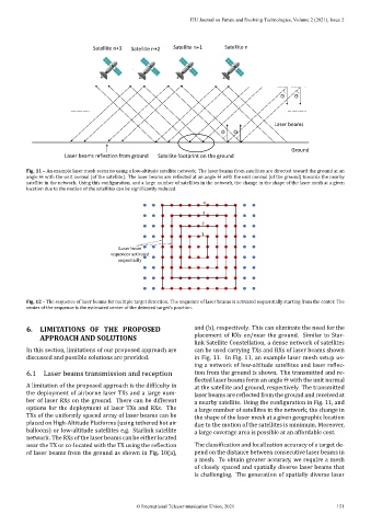
Fig. 11 – An example laser mesh scenario using a low‑altitude satellite network. The laser beams from satellites are directed toward the ground at an
angle Θ with the unit normal (of the satellite). The laser beams are re lected at an angle Θ with the unit normal (of the ground) towards the nearby
satellite in the network. Using this con iguration, and a large number of satellites in the network, the change in the shape of the laser mesh at a given
location due to the motion of the satellites can be signi icantly reduced.
4
3
2
1
Laser beam
sequences activated
sequentially
Fig. 12 – The sequence of laser beams for multiple target detection. The sequence of laser beams is activated sequentially starting from the center. The
center of the sequence is the estimated center of the detected target’s position.
6. LIMITATIONS OF THE PROPOSED and (b), respectively. This can eliminate the need for the
APPROACH AND SOLUTIONS placement of RXs on/near the ground. Similar to Star‑
link Satellite Constellation, a dense network of satellites
In this section, limitations of our proposed approach are can be used carrying TXs and RXs of laser beams shown
discussed and possible solutions are provided. in Fig. 11. In Fig. 11, an example laser mesh setup us‑
ing a network of low‑altitude satellites and laser re lec‑
6.1 Laser beams transmission and reception tion from the ground is shown. The transmitted and re‑
lected laser beams form an angle Θ with the unit normal
A limitation of the proposed approach is the dif iculty in at the satellite and ground, respectively. The transmitted
the deployment of airborne laser TXs and a large num‑ laser beams are re lected from the ground and received at
ber of laser RXs on the ground. There can be different a nearby satellite. Using the con iguration in Fig. 11, and
options for the deployment of laser TXs and RXs. The a large number of satellites in the network, the change in
TXs of the uniformly spaced array of laser beams can be the shape of the laser mesh at a given geographic location
placed on High‑Altitude Platforms (using tethered hot air due to the motion of the satellites is minimum. Moreover,
balloons) or low‑altitude satellites e.g. Starlink satellite a large coverage area is possible at an affordable cost.
network. The RXs of the laser beams can be either located
near the TX or co‑located with the TX using the re lection The classi ication and localization accuracy of a target de‑
of laser beams from the ground as shown in Fig. 10(a), pend on the distance between consecutive laser beams in
a mesh. To obtain greater accuracy, we require a mesh
of closely spaced and spatially diverse laser beams that
is challenging. The generation of spatially diverse laser
© International Telecommunication Union, 2021 151