
Page 127 - ITU Journal Future and evolving technologies – Volume 2 (2021), Issue 2
P. 127
ITU Journal on Future and Evolving Technologies, Volume 2 (2021), Issue 2
Node k
TX RF Chain 1 TX 1
Upsample
Pulse Shape DAC PA
Upconversion
TX RF Chain TX
Upsample
Pulse Shape DAC PA
TX Digital Upconversion
Beamforming MUX N MUX 1
Analog
Canceller
Tap N Tap 1
Delay N Delay 1 Self-interference
channel
Joint Cancellation Phase Phase
and Beamforming Tap settings Shifter Shifter
Design MUX/DEMUX settings N 1
Attenuator Attenuator
N 1
DEMUX N DEMUX 1
RX Digital
Beamforming RX RF Chain 1 RX 1
Matched Filter
Downsample ADC LNA
Downconversion Adder 1,N Adder 1,1
RX RF Chain RX
Matched Filter
Downsample ADC LNA
Downconversion Adder ,N Adder ,1
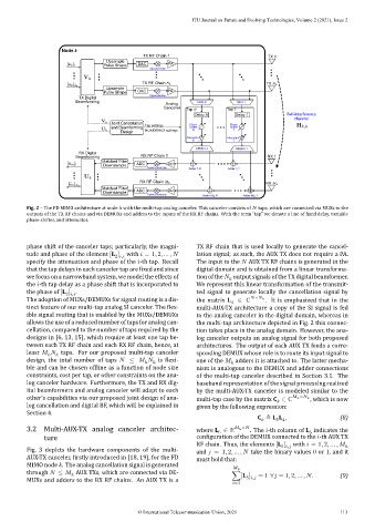
Fig. 2 – The FD MIMO architecture at node with the multi‑tap analog canceler. This canceler consists of taps, which are connected via MUXs to the
outputs of the TX RF chains and via DEMUXs and adders to the inputs of the RX RF chains. With the term “tap” we denote a line of ixed delay, variable
phase shifter, and attenuator.
phase shift of the canceler taps; particularly, the magni‑ TX RF chain that is used locally to generate the cancel‑
tude and phase of the element [L ] with = 1, 2, … , lation signal; as such, the AUX TX does not require a PA.
2 ,
specify the attenuation and phase of the ‑th tap. Recall The input to the AUX TX RF chains is generated in the
that the tap delays in each canceler tap are ixed and since digital domain and is obtained from a linear transforma‑
we focus on a narrowband system, we model the effects of tion of the output signals of the TX digital beamformer.
the ‑th tap delay as a phase shift that is incorporated to We represent this linear transformation of the transmit‑
the phase of [L ] . ted signal to generate locally the cancellation signal by
2 ,
The adoption of MUXs/DEMUXs for signal routing is a dis‑ the matrix L 4 ∈ ℂ × . It is emphasized that in the
tinct feature of our multi‑tap analog SI canceler. The lex‑ multi‑AUX‑TX architecture a copy of the SI signal is fed
ible signal routing that is enabled by the MUXs/DEMUXs to the analog canceler in the digital domain, whereas in
allows the use of a reduced number of taps for analog can‑ the multi‑tap architecture depicted in Fig. 2 this connec‑
cellation, compared to the number of taps required by the tion takes place in the analog domain. However, the ana‑
designs in [6, 13, 15], which require at least one tap be‑ log canceler outputs an analog signal for both proposed
tween each TX RF chain and each RX RF chain, hence, at architectures. The output of each AUX TX feeds a corre‑
least taps. For our proposed multi‑tap canceler sponding DEMUX whose role is to route its input signal to
design, the total number of taps ≤ is lexi‑ one of the adders it is attached to. The latter mecha‑
ble and can be chosen of line as a function of node size nism is analogous to the DEMUX and adder connections
constraints, cost per tap, or other constraints on the ana‑ of the multi‑tap canceler described in Section 3.1. The
log canceler hardware. Furthermore, the TX and RX dig‑ baseband representation of the signal processing realized
ital beamformers and analog canceler will adapt to each by the multi‑AUX‑TX canceler is modeled similar to the
other’s capabilities via our proposed joint design of ana‑ multi‑tap case by the matrix C ∈ ℂ × , which is now
log cancellation and digital BF, which will be explained in given by the following expression:
Section 4.
C ≜ L L , (8)
5 4
3.2 Multi‑AUX‑TX analog canceler architec‑ where L ∈ ℝ × . The ‑th column of L indicates the
5
5
ture con iguration of the DEMUX connected to the ‑th AUX TX
RF chain. Thus, the elements [L ] with = 1, 2, … ,
5 ,
Fig. 3 depicts the hardware components of the multi‑ and = 1, 2, … , take the binary values 0 or 1, and it
AUX‑TX canceler, irstly introduced in [18, 19], for the FD must hold that:
MIMO node . The analog cancellation signal is generated
through ≤ AUX TXs, which are connected via DE‑ ∑[L ] = 1 ∀ = 1, 2, … , . (9)
MUXs and adders to the RX RF chains. An AUX TX is a 5 ,
=1
© International Telecommunication Union, 2021 113