
Page 57 - ITU KALEIDOSCOPE, ATLANTA 2019
P. 57
ICT for Health: Networks, standards and innovation
There are no such differences as the foot prosthetic moves reliability, etc. must be defined in standardization. On the
synchronously with the healthy foot. However, a sensor that other hand, since a computer system controls several
monitors the healthy foot is needed. From our existing modules in a powered prosthetic, not only physical
research, we determined that monitoring the heel position of information but also data-level information must be
the healthy foot is best. This is why a sensor is built into the standardized.
heel of the shoe.
The following eight interfaces shown in Figure 12 do not
The central terminal is required to control the instep have exchange information between modules, so their
push/pull module in collaboration with the control board. We interface level is physical:
believe the upper position of the foot module is ideal for - INT-1: size, connection method, and reliability
mounting the battery and control board to the foot prosthetic. between socket and ankle joint;
- INT-2: size, connection method, and reliability
We plan to use a single motor cylinder for the instep between ankle joint and instep push/pull;
push/pull module. The module is attached to the front of the - INT-3: size, connection method, and reliability
shin as shown in Figure 12. However, we plan to determine between ankle joint and foot;
whether the module should be placed on the front of shin or - INT-4: size, connection method, and reliability
on part of the Achilles' tendon on the basis of experimental between instep push/pull and foot;
results. - INT-5: size, connection method, and reliability
between foot and toe;
For the single motor cylinder, we used an Oriental Motor DR - INT-6: size, connection method, and reliability
series with a 30-mm stroke, 2-kg carrying force, and a 100- between heel sensor and shoe;
mm/sec maximum stroke speed [11]. The heel-up spring has - INT-7: DC/AC, voltage, and connector type between
a motor-driven spring-release mechanism. However, we battery and instep push/pull;
estimate that the release timing must be controlled by a - INT-8: DC/AC, voltage, and connector type between
sensor built into the heel-up spring, not one built into the heel battery and toe.
of a shoe for a healthy foot.
On the other hand, the following four interfaces include data-
We estimate the instep push/pull module and heel-up spring level information in addition to the physical level
can be applied to people with walking disabilities. In information;
particular, the heel-up spring is useful as it compensates for - INT-9:
muscle weakness, as described in section 4. This means that Physical level: connector type;
the price of the heel-up spring can be lowered. Data level: pulses from the control board to the
instep. The control board changes the direction,
speed and number of pulses to control the cylinder
speed and stroke.
- INT-10:
Physical level: connector type;
Data level: pulses from the control board to a
cylinder of the toe module. The control board
changes the direction, speed and number of pulses
to control the cylinder speed and stroke.
- INT-11:
Physical to session level: wireless connection
(Bluetooth);
Application level: controls direction, speed and
maximum angle of foot rotation.
- INT-12:
Physical to session level: wireless connection
(Bluetooth);.
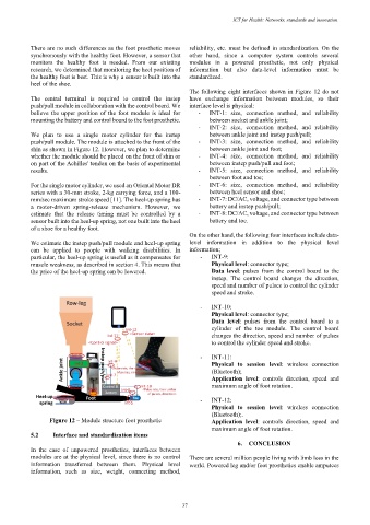
Figure 12 – Module structure foot prosthetic Application level: controls direction, speed and
maximum angle of foot rotation.
5.2 Interface and standardization items
6. CONCLUSION
In the case of unpowered prosthetics, interfaces between
modules are at the physical level, since there is no control There are several million people living with limb loss in the
information transferred between them. Physical level world. Powered leg and/or foot prosthetics enable amputees
information, such as size, weight, connecting method,
– 37 –