
Page 989 - 5G Basics - Core Network Aspects
P. 989
Transport aspects 2
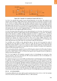
Figure 13-8 – Example L2.1 transmission format for N=2, MSF = 8
The PSD of the upstream RMC symbols may be reduced during the L2.1 link states. The number of used
upstream data subcarriers in RMC symbols may be reduced during the L2.1 link states. The particular value
of PSD reduction L2_PSDRus relative to L0, the highest subcarrier on which the PSD reduction is applied
(fL2_PSDR-US), the set of upstream active data subcarriers and the bit loading of active data subcarriers, are
determined at the entry into an L2.1 link state by the L2.1-Entry-Request eoc command and response (see
clause 11.2.2.16). The indices and parameters (bi, gi) of RMC subcarriers at the transition into an L2.1 link
state shall be kept the same as were assigned during L0. In L2.1 link states, the indices and parameters of
the RMC subcarriers may change through the RPA procedure.
The PSD of the downstream RMC symbols may be reduced during the L2.1 link states. The number of used
downstream data subcarriers in RMC symbols may be reduced during the L2.1 link states. The particular
value of PSD reduction L2_PSDRds, the highest subcarrier on which it is applied (fL2_PSDR-DS), the set of
downstream active data subcarriers and the bit loading of active data subcarriers, and the relative gain
compensation factors are determined at the entry into an L2.1 link state by the L2.1-Entry-Request eoc
command and response (see clause 11.2.2.16). The indices and bi values of RMC subcarriers at the
transition into an L2.1 link state shall be kept the same as were assigned during L0. In L2.1 link states, the
indices and parameters of the RMC subcarriers may change through the RPA procedure.
The L2_PSDRus and L2_PSDRds can be adjusted by steps of 1dB and shall not exceed the value of
L2_PSDR_max; the valid range of L2_PSDR is from 0 to 10 dB. The value of L2_PSDR in both directions
determines the flat cutback on the tssi in L2.1 and L2.2, which shall be applied on the subcarriers with
indices ranging from 0 to fL2_PSDR of the corresponding transmission direction. No cutback shall be applied on
subcarriers with indices greater than fL2_PSDR.
NOTE – In the upstream direction, reduction of tssi by L2_PSDR will result in reduction of the PSD on the U-R interface
by L2_PSDR. In the downstream direction, reduction of tssi by L2_PSDR will result in reduction of the PSD on the U-R
interface by L2_PSDR. However, on the U-O interface this reduction may be somewhat less than L2_PSDR due to
presence of pre-compensation signals.
The FTU-R shall apply the PSD reduction requested by the L2.1-Entry-Request eoc command in the
upstream direction. The FTU-O shall apply the PSD reduction indicated by the L2.1-Entry-Request eoc
command in the downstream direction.
Sync symbols during the L2.1 link state shall be transmitted at their standard positions of every superframe.
For upstream, the PSD reduction for sync symbols shall be the same as the PSD reduction of the RMC
symbols, and all sync symbol subcarriers that are active during L0 shall stay active in both L2.1N and L2.1B
link states. The gi on the upstream subcarriers located at the frequencies that become unused on the RMC
symbols at the L2.1 entry shall have the same gi as in the L0 state in both the L2.1N and L2.1B link states. If
some upstream subcarriers on the RMC symbols become unused at the L2.1 entry, the gi on those
subcarriers may differ between the sync symbols and RMC symbols. For downstream, the PSD reduction for
sync symbols shall be the same as the PSD reduction of the RMC symbols and all sync symbol subcarriers
that are active during L0 shall stay active in both L2.1N and L2.1B link states (the same gi as in the L0 state).
13.4.1.2 L2.1 entry procedure
The procedure defined in this clause shall be used to transition from L0 into L2.1N or L2.1B. The transition
times for L2.1N and L2.1B link states defined in Table 12-1 shall be applied.
979