
Page 988 - 5G Basics - Core Network Aspects
P. 988
2 Transport aspects
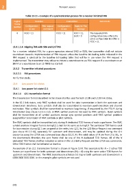
Table 13-11 – Example of a synchronization process for a receiver initiated FRA
Logical Receiver Transmitter Comments
frame
number Configuration FRA request Configuration Reply to FRA
in use command in use message
6 FCCC = 11 FCCC = 11 FCCC = 11, The requested FRA
LFDC = 0 configuration takes effect, the
active configuration identifier is
FCCC = 11.
13.3.1.1.4 Aligning FRA with SRA and L2-TRNS
For a receiver initiated FRA, for a given operation interval (NOI or DOI), the transmitter shall not initiate
countdown towards implementation of FRA request unless the baseline bit-loading table indicated in the
FRA request is identical to the baseline bit-loading table that will be in use when the FRA request is
implemented. The transmitter may refuse to initiate a countdown to an FRA request if a countdown to an
SRA-R or a countdown to an L2-TRNS has started.
13.3.2 Transmitter initiated procedures
13.3.2.1 FRA procedures
For further study.
13.4 Low power link states
13.4.1 Low power link state L2.1
13.4.1.1 L2.1 transmission format
The transmission format described in this clause shall be used for both L2.1N and L2.1B link states.
In the L2.1 link states, only RMC symbols shall be used for data transmission in both the upstream and
downstream directions. Sync symbols shall also be transmitted to maintain synchronization and channel
estimation. Pilot symbols shall be transmitted to maintain loop timing, if requested by the FTU-R during
initialization (see clause 12.3.3.2.12), at RMC symbol positions not used by RMC symbols. Quiet symbols
shall be transmitted at all symbol positions except sync symbol positions and RMC symbol positions
assigned for transmission of RMC symbols or pilot symbols.
The RMC symbols shall be transmitted only during N dedicated TDD frames of each superframe. The RMC
symbol position in logical frames during L2.1 shall be the same as during L0. The particular TDD frames used
for transmission during L2.1 are assigned at the entry into L2.1, by the L2.1-Entry-Request eoc command
(see clause 11.2.2.16), separately for upstream and downstream, and may be updated during the L2.1
session by using the L2TSA eoc command (see clause 13.2.1.4). The valid values of N are from 2 to MSF. In
the downstream direction, the sync frame shall be one of the N dedicated TDD frames. All of the N
dedicated TDD frames shall be indicated as active in the L2.1-Entry-Request and the L2TSA eoc commands.
Other TDD frames shall be indicated as inactive.
An example of an L2.1 transmission format is shown in Figure 13-8. This example is for N = 2 active TDD
frames per superframe for both upstream and downstream (MSF = 8) using the same active TDD frames for
upstream and downstream. The RMC transmission schedule bit map in both upstream and downstream is
0000 0000 0001 0001. In this example, pilot symbols are not used.
978