
Page 987 - 5G Basics - Core Network Aspects
P. 987
Transport aspects 2
13.3.1.1.3 Timing and synchronization for receiver initiated FRA
Two counts are used to maintain synchronization between the configurations requested via FRA (see
Table 9-10 to Table 9-14) at the transmitter and the receiver ends:
1) The 4-bit FRA configuration change count (FCCC) is used to identify the particular configuration to
be used. The FCCC shall be incremented whenever a new configuration change is initiated by the
receiver and shall wrap around at count 11112, i.e., incrementing from 11112 to 00002. In this way,
the FCCC serves as a unique identifier for the configuration to be used.
The FCCC is incremented separately for the NOI and DOI active bit loading tables.
2) The 4-bit FRA logical frame down count (LFDC) is used by the transmitter to indicate when a new
configuration shall take effect. The initial LFDC value P0 is first set by the Reply to FRA request
command. In the following P0 logical frames the Reply to FRA commands shall include LFDC values
decreased by 1 in every subsequent logical frame. The LFDC value is updated until reaching the
value zero which indicates the activation time of the new configuration. The new FRA
configuration shall take effect from the first symbol in the logical frame for which the expected
LFDC indicated in the reply to FRA RMC command is 0. Further, the FTU shall update the identifier
of the active bit-loading table accordingly (see Table 9-5 and Table 9-8 for the current active bit-
loading table identifier field and Table 9-13 and Table 9-14 for the reply to FRA request
commands).
All FRA requests with the same FCCC shall be considered identical. The transmitter shall discard FRA
requests with an FCCC equal to or lower than the one currently in use, taking wraparound into account.
The allowed minimum initial LFDC shall be an indicated capability of the receiver exchanged during
initialization (see parameter MB upstream in Table 12-41 and parameter MB downstream in Table 12-44).
The maximum bound for the initial LFDC is 15.
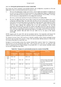
Example of a synchronization process for a receiver initiated FRA is given in Table 13-11. It depicts the
transition from one FRA configuration (with FCCC = 10) to another one, with FCCC = 11, using the initial
LFDC of 3 repeating the FRA change indication 3 times (with LFDC = 2, 1 and 0) by the transmitter before
the new FRA configuration takes effect.
Table 13-11 – Example of a synchronization process for a receiver initiated FRA
Logical Receiver Transmitter Comments
frame
Configuration FRA request Configuration Reply to FRA
number
in use command in use message
Initial FCCC = 10 FCCC = 10
stage
1 FCCC = 10 FCCC = 11 FCCC = 10 Receiver initiates FRA request
for a new configuration with
FCCC = 11.
2 FCCC = 10 FCCC = 11 FCCC = 10 The receiver may repeat the
same request using the same
FCCC.
3 FCCC = 10 FCCC = 10 FCCC = 11, Transmitter replies to the FRA
LFDC = 3 request message with a reply to
FRA command and indicates
the configuration change after
three logical frames.
4 FCCC = 10 FCCC = 10 FCCC = 11,
LFDC = 2
5 FCCC = 10 FCCC = 10 FCCC = 11,
LFDC = 1
977