
Page 957 - 5G Basics - Core Network Aspects
P. 957
Transport aspects 2
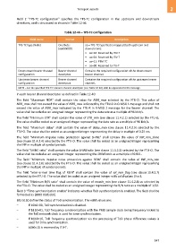
Field 2 "TPS-TC configuration" specifies the TPS-TC configuration in the upstream and downstream
directions, and is structured as shown in Table 12-46.
Table 12-46 – TPS-TC configuration
Field name Format Description
TPS-TC type (Note) One byte: aa = TPS-TC type that is mapped (both upstream and
[aa000000] downstream):
• aa=10: Reserved by ITU-T
• aa=01: Reserved by ITU-T
• aa=11: PTM-TC
• aa=00: Reserved to ITU-T
Downstream bearer channel Bearer channel Contains the required configuration of the downstream
configuration descriptor bearer channel.
Upstream bearer channel Bearer channel Contains the required configuration of the upstream bearer
configuration descriptor channel.
NOTE – For the specified TPS-TC a bearer channel descriptor (see Table 12-40) shall be appended to the message.
In each bearer channel descriptor as defined in Table 12-40:
The field "Maximum NDR” shall contain the value for NDR_max selected by the FTU-O. This value of
NDR_max shall not exceed the value of NDR_max indicated by the FTU-O in O-MSG 1 message and shall not
exceed the value of NDR_max indicated by the FTU-R in R-MSG 2 message for the bearer channel. The
value shall be coded as an unsigned integer representing the data rate as a multiple of 96 kbit/s.
The field "Minimum ETR" shall contain the value of ETR_min (see clause 11.4.2.1) selected by the FTU-O.
The value shall be coded as an unsigned integer representing the data rate as a multiple of 96 kbit/s.
The field "Maximum delay" shall contain the value of delay_max (see clause 11.4.2.3) selected by the
FTU-O. The value shall be coded as an unsigned integer representing the delay in multiple of 0.25 ms.
The field "Minimum impulse noise protection against SHINE" shall contain the value of INP_min_shine
(see clause 11.4.2.4) selected by the FTU-O. The value shall be coded as an unsigned integer representing
the INP in multiple of symbol periods.
The field "SHINE ratio" shall contain the value SHINEratio (see clause 11.4.2.5) selected by the FTU-O. The
value shall be coded as an unsigned integer representing the SHINEratio as a multiple of 0.001.
The field "Minimum impulse noise protection against REIN" shall contain the value of INP_min_rein
(see clause 11.4.2.6) selected by the FTU-O. The value shall be coded as an unsigned integer representing
the INP in multiple of symbol periods.
The field "Inter-arrival time flag of REIN" shall contain the value of iat_rein_flag (see clause 11.4.2.7)
selected by the FTU-O. The value shall be coded as an unsigned integer with valid values 0 to 3.
The field "Minimum R/N ratio" shall contain the value of rnratio_min (see clause 11.4.2.8) as selected by
the FTU-O. The value shall be coded as an unsigned integer representing the R/N ratio as a multiple of 1/32.
Field 3 "Time synchronization enable" indicates whether ToD synchronization is enabled. The field shall be
formatted as [0000 0b2b1b0].
Bits b1b0 define the status of ToD synchronization. The valid values are:
– If b1b0=00, ToD synchronization is disabled.
– If b1b0=01, ToD frequency synchronization with the PMD sample clock being frequency locked to
the ToD network clock is used for time synchronization.
– If b1b0=10, ToD frequency synchronization via the processing of ToD phase difference values is
used for time synchronization.
– b1b0=11 is reserved by ITU-T.
947