
Page 955 - 5G Basics - Core Network Aspects
P. 955
Transport aspects 2
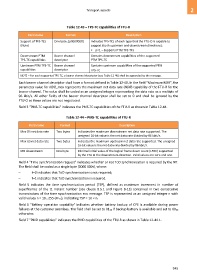
Table 12-43 – TPS-TC capabilities of FTU-R
Field name Format Description
Support of TPS-TCs One byte: [p0000000] Indicates TPS-TCs of each type that the FTU-O is capable to
(Note) support (both upstream and downstream directions):
• p=1 – Supports PTM TPS-TCs
Downstream PTM Bearer channel Contains downstream capabilities of the supported
TPS-TC capabilities descriptor PTM TPS-TC
Upstream PTM TPS-TC Bearer channel Contains upstream capabilities of the supported PTM
capabilities descriptor TPS-TC
NOTE – For each supported TPS-TC, a bearer channel descriptor (see Table 12-40) shall be appended to the message.
Each bearer channel descriptor shall have a format defined in Table 12-40. In the field "Maximum NDR", the
parameter value for NDR_max represents the maximum net data rate (NDR) capability of the FTU-R for the
bearer channel. The value shall be coded as an unsigned integer representing the data rate as a multiple of
96 kbit/s. All other fields of the bearer channel descriptor shall be set to 0 and shall be ignored by the
FTU-O as those values are not negotiated.
Field 3 "PMS-TC capabilities" indicates the PMS-TC capabilities of the FTU-R as shown in Table 12-44.
Table 12-44 – PMS-TC capabilities of FTU-R
Field name Format Description
Max DS net data rate Two bytes Indicates the maximum downstream net data rate supported. The
unsigned 16-bit value is the net data rate divided by 96 kbit/s.
Max US net data rate Two bytes Indicates the maximum upstream net data rate supported. The unsigned
16-bit value is the net data rate divided by 96 kbit/s.
MB downstream One byte Minimal initial value of the logical frame down count (LFDC) supported
by the FTU in the downstream direction. Valid values are zero and one.
Field 4 "Time synchronization request" indicates whether or not ToD synchronization is required by the NT.
The field shall be coded as a single byte [0000 000t], where:
– t=0 indicates that ToD synchronization is not required;
– t=1 indicates that ToD synchronization is required.
Field 5 indicates the time synchronization period (TSP), defined as maximum increment in number of
superframes of the t1 instant number (see clause 8.5.1 and Figure 8-13) contained in two consecutive
transmissions of the time synchronization eoc message. TSP is represented as an unsigned integer n with
valid values n = 10…255 (FF16), indicating TSP = 16 × n.
Field 6 "Battery operation capability" indicates whether battery backup of CPE is available during power
failures at the customer premises. The field shall be set to 0116 if backup battery is available and set to 0016
otherwise.
Field 7 "PMD capabilities" indicates the PMD capabilities of the FTU-R as shown in Table 12-44.1.
945