Page 870 - 5G Basics - Core Network Aspects
P. 870
2                                                 Transport aspects


            QLN(f) is measured during sync symbol positions, when sync symbols that have all subcarriers masked are
            transmitted on this line and on all other lines in the vector group that this line belongs to. Sync symbols
            that have all subcarriers masked correspond to elements in the probe sequence with value 0 as defined in
            clause 10.2.2.1.

            The QLN(f) per subcarrier group shall be measured by the VCE during showtime L0 link state only, and shall
            be updated during showtime L0 link state only, on request of the DPU ME in response to an update test
            parameters request (see clause 7.1.9.1 of [ITU-T G.997.2]).

            The objective is to provide means by which the quiet line noise PSD at the U-O reference point (referred to
            as  upstream  QLN)  and  at  the  U-R  reference  point  (referred  to  as  downstream  QLN)  can  be  accurately
            identified. Upstream QLN is referred to the U-O reference point and downstream QLN is referred to the U-R
            reference  point  by  removing  the  effects  of  the  corresponding  receiver  filter  characteristics  function,
            assuming the receiving FTU presents a load impedance to the network of 100 Ohms resistive (see Note 1).

            NOTE 1 – In actual implementations, the receiving FTU load impedance may deviate from 100 Ohms resistive.
            For downstream QLN, the FTU-R reported DFT output samples as specified in clause 10.3.3.2 can be used
            (DFT samples are referenced to a termination impedance (i.e,. load impedance of the FTU transmitter to
            the network) of 100 Ohms resistive).

            For upstream QLN, the FTU-O's internal measurements are used.
            The  VCE  shall  average  the  measurements  over  Navg  of  at  least  =  256 symbols  (consecutive  or  non-
            consecutive), and shall indicate the measurement value of Navg, represented as a 16-bit unsigned value.
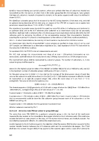
            The reported QLN values shall be represented by subcarrier groups. The number of subcarriers, G, in one
            subcarrier group shall be equal to:
                                                G ≤ max(2 ceiling(log ((Θ+1)/512)) , 1)
                                                               2
            where Θ is the highest subcarrier index of the MEDLEY set (either MEDLEYds set or MEDLEYus set), and 512
            is the maximum number of subcarrier groups. Valid values of G are 1, 2 and 4.

            For the given group size G, QLN(k × G × fSC) shall be the average of the linear power values of quiet line
            noise on the subcarriers with indices from k × G to ((k+1) × G) –1. QLN shall be expressed in dBm/Hz. It shall
            be  represented  as  an  eight-bit  unsigned  integer  n(k),  where  the  valid  values  of  k  are  from  k  =  0  to
            ceiling(Θ/G). The value of n(k) shall be coded so that:
                                           QLN(k × G ×fSC) = −35 − (n(k)/2) dBm/Hz.

            This format supports a QLN(f) granularity of 0.5 dB with a range of values for QLN(f) from −35.5 dBm/Hz to
            −160.0 dBm/Hz , corresponding to the set of valid values of n = 1 to 250.

            A special value n = 0 indicates a value of QLN = –35 dBm/Hz or higher
            A special value n = 251 indicates a value of QLN = –160.5 dBm/Hz or lower. A special value n = 254 indicates
            that  no  measurement  could  be  done  for this  subcarrier  group  because  none of  its  subcarriers  is  in  the
            MEDLEY set with gi > 0.

            A special value n = 255 indicates that the parameter is undetermined.
            All other values are reserved by ITU-T.

            11.4.1.2.4    Active line noise PSD per subcarrier group (ALN-psg)
            The  active  line  noise  PSD  ALN(f)  for  a  particular  subcarrier  group  is  the  rms  level  of  the  total  noise
            measured by the receiver at the constellation de-mapper referred to the U reference point. This total noise
            includes the extrinsic noise present on the loop, all FTU receiver internal noises, and residual crosstalk. The
            level shall be expressed in dBm/Hz. It is defined for downstream only.
            In referring back to the U-R reference point, the objective is that the receive PMD function accounts for the
            receiver transfer function between the U-R reference point and the constellation de-mapper. The FTU-R
            shall take into account the gain (AGC) it has applied to the received signal and do a best effort attempt to


            860

