
Page 867 - 5G Basics - Core Network Aspects
P. 867
Transport aspects 2
RS is a reference impedance, corresponding to the source impedance. RL is a reference impedance,
corresponding to the load impedance.
For the purpose of Hlog definition, RS and RL shall both be 100 ohms resistive.
NOTE 1 – The values of RS and RL used for the Hlog definition do not imply specific values for FTU implementations.
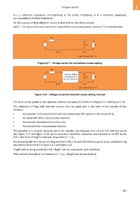
Figure 11-7 – Voltage across the load without access cabling
Figure 11-8 – Voltage across the load with access cabling inserted
The same can be applied to the upstream direction (swapping U-O and U-R in Figure 11-7 and Figure 11-8).
The calculation of Hlog shall take into account that the signal path is the result of the cascade of four
functions:
• the precoder in the downstream and post-processing in the upstream (see clause 10.3);
• the transmitter filter characteristics function;
• the channel characteristics function; and
• the receiver filter characteristics function.
The objective is to provide means by which the insertion loss between the U-O and U-R reference points
(see Figure 11-7 and Figure 11-8) can be accurately identified, estimated, and reported to the ME by the
VCE in the form of Hlog(f) at discrete frequencies f = i × fSC.
The following definition allows the Hlog referred to the U-O and U-R reference points to be calculated using
equivalents of U1 and U2 in Figure 11-7 and Figure 11-8.
Hlog(f) shall be computed by the VCE. Hlog(f) shall be computed in both directions.
With the definition above, for frequency f = i × fSC, Hlog(f) shall be calculated as:
857