Page 868 - 5G Basics - Core Network Aspects
P. 868
2 Transport aspects
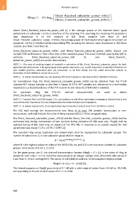
Direct_Rec eived_subc arrier_pow er_mW(i )
Hlog ( ) f 10 log 10
Direct_Tra nsmit_subc arrier_pow er_mW(i ) ,
where Direct_Received_subcarrier_power_mW (i) is the average power of the received direct signal
component on subcarrier i at the U-interface of the receiving FTU, assuming the receiving FTU presents a
load impedance RL to the network of 100 Ohms resistive (see Note 2), and
Direct_Transmit_subcarrier_power_mW(i) is the average power of the transmit direct signal component on
subcarrier i at the U-interface of the transmitting FTU, assuming the network input impedance is 100 Ohms
resistive (see Note 3 and Note 4).
Direct_Received_subcarrier_power_mW(i) and Direct_Transmit_subcarrier_power_mW(i) should not
include FEXT contributions from other lines of the vectored group. The exact methods used by the VCE to
estimate Direct_Received_subcarrier_power_mW (i) and Direct_Transmit_
subcarrier_power_mW(i) are vendor discretionary.
NOTE 1 – One way of avoiding impact of crosstalk in estimation of the Direct_Received_subcarrier_power for both
upstream and downstream is by applying particular probe sequences, e.g., probe sequences containing 0-elements on
sync symbol positions associated with the estimation on all lines except the line under estimation (similar to
estimation of QLN defined in clause 11.4.1.2.3).
NOTE 2 – In actual implementations, the receiving FTU load impedance may deviate from 100 Ohms resistive.
For downstream Hlog, the Direct_Received_subcarrier_power_mW(i) can be obtained from the FTU-R
reported DFT output samples as specified in clause 10.3.3.2 (DFT samples are referenced to a termination
impedance (i.e. load impedance of the FTU receiver to the network) of 100 Ohms resistive).
For upstream Hlog, the FTU-O's internal measurements are used to obtain
Direct_Received_subcarrier_power_mW(i).
NOTE 3 – Transmit PSD in G.9700 clause 7.3 is also defined on 100 Ohms termination impedance. Remark that in this
case termination impedance is to be interpreted as the network/loop input impedance.
NOTE 4 – In actual deployments, the network/loop input impedance may deviate from 100 Ohms resistive.
The VCE shall average the measurements over Navg of at least 256 symbols (consecutive or non-
consecutive), and shall indicate the value of Navg represented as a 16-bit unsigned value.
The Direct_Received_subcarrier_power_mW (i) and the Direct_Transmit_subcarrier_power_mW(i) shall be
estimated only during transmission of sync symbols during showtime L0 link state only. Hlog(f) shall be
updated during L0 link state only, on request of the DPU ME, in response to an update request for test
parameters (see clause 7.1.9.1 of [ITU-T G.997.2]).
The reported Hlog values (upstream and downstream) shall be represented by subcarrier groups. The
number of subcarriers, G, in one subcarrier group shall be equal to:
G = max(2 ceiling(log ((Θ+1)/512)) , 1),
2
where Θ is the highest subcarrier index of the MEDLEYds set, and 512 is the maximum number of subcarrier
groups. Valid values of G are 1, 2 and 4.
For the given group size G, the channel characteristics function Hlog(k × G × fSC) is the value of Hlog at
subcarrier with index i = k × G. It shall be represented by an integer number m(k), where the valid values of
k are from k = 0 to k =ceiling(Θ/G). The values of m(k) shall be coded as 10-bit unsigned integers so that:
Hlog(k × G × fSC ) = 6 − (m(k)/10).
This format supports an Hlog(f) granularity of 0.1 dB with a valid range of values from +5.9 dB to −95.9 dB,
corresponding to the set of valid values of m = 1 to 1019.
858

