
Page 847 - 5G Basics - Core Network Aspects
P. 847
Transport aspects 2
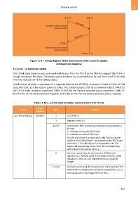
Figure 11-6 – Timing diagram of the downstream probe sequence update
command and response
11.2.2.16 L2 transition control
The L2 link state transition eoc command shall be sent from the FTU-O to the FTU-R to request the FTU-R to
change low power link state. The battery powered status eoc command shall be sent from the FTU-R to the
FTU-O to indicate the FTU-R battery status.
The first byte of either a command or a response shall be the OPCODE, as shown in Table 11-3 for L2 link
state and Table 11-5 for battery powered status. The remaining bytes shall be as shown in Table 11-48.1 for
the L2 link state transition command, Table 11-48.5 for the battery powered status command, Table 11-
48.6 for the L2 link state transition response, and Table 11-48.7 for the battery powered status response.
Table 11-48.1 – L2 link state transition command (FTU-O to FTU-R)
Length
Name Byte Content
(Bytes)
L2.1-Entry-Request Variable 2 0116 (Note 1)
3 Segment code (SC)
4 and 5 Downstream RMC transmission schedule represented as a
bit map:
0 – indicates an inactive TDD frame
1 – indicates an active TDD frame
The LSB of the byte 5 corresponds to the TDD sync frame
(index 0). The MSB of byte 5 corresponds to the TDD frame
with index 7. The LSB of byte 4 corresponds to the TDD
frame with index 8 (see clause 10.6). Bits corresponding
with indices ≥ MSF shall be set to 0.
6 One octet containing the downstream L2 PSD power
reduction (L2_PSDRds) value in the range from 0 to 10 dB
reduction in units of 1 dB, represented as an unsigned
integer.
7 and 8 Two bytes containing the last subcarrier index on which the
downstream L2 PSDR power reduction is applied (fL2_PSDR-DS).
Valid values are in the range from 0 to NSC-1.
837