Page 848 - 5G Basics - Core Network Aspects
P. 848

2                                                 Transport aspects


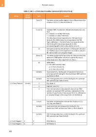
                              Table 11-48.1 – L2 link state transition command (FTU-O to FTU-R)

                                 Length
                   Name                         Byte                            Content
                                 (Bytes)
                                              9 and 10     Two bytes containing the minimal value of downstream BDR
                                                           in bytes in L2.1, L2.1_BDR_min (Note 3)


                                             11 and 12     Upstream RMC transmission schedule represented as a bit
                                                           map:
                                                           0 – indicates an inactive TDD frame
                                                           1 – indicates an active TDD frame
                                                           The LSB of byte 10 corresponds to the TDD sync frame
                                                           (index 0). The MSB of byte 10 corresponds to the TDD
                                                           frame with index 7. The LSB of byte 9 corresponds to the
                                                           TDD frame with index 8 (see clause 10.6). Bits
                                                           corresponding with indices ≥ MSF shall be set to 0.
                                                13         One octet containing the upstream L2 PSD power reduction
                                                           (L2_PSDRus) value in the range from 0 to 10 dB in units of 1
                                                           dB, represented as an unsigned integer.
                                             14 and 15     Two bytes containing the last subcarrier index on which the
                                                           upstream L2 PSD power reduction is applied (fL2_PSDR-US).
                                                           Valid values are in the range from 0 to NSC-1.

                                                16         [0000 000a]
                                                           a = Link state transition type:
                                                           -  a = 0: from L0 to L2.1N.
                                                           -  a = 1: from L0 to L2.1B.
                                              Variable     Used subcarriers, relative gain compensation factors (ri),
                                                           and proposed bit loading for the downstream RMC symbols
                                                           (see Table 11-48.3)
                                              Variable     DTU framing parameters, and bit loading for the upstream
                                                           RMC symbols (see Table 11-48.2)

             L2.2-Entry-Request   Variable       2         0216 (Note 1)
                                                 3         Segment code (SC)
                                                 4         Time interval between two adjacent downstream RMC
                                                           symbols  (or upstream RMC symbols)  represented in the
                                                           number of superframes X (see clause 13.4.2.1), indicated as
                                                           an unsigned integer in the range from 1 to 32 (Note 2)


                                              5 and 6      Two bytes containing the minimum BDR in bytes in L2.2,
                                                           L2.2_BDR_min (Note 3)
                                              Variable     Used subcarriers and proposed bit loading for the
                                                           downstream RMC symbols (see Table 11-48.4) (Note 4)


                                              Variable     DTU framing parameters, and bit loading for the upstream
                                                           RMC symbols (see Table 11-48.2)

             L2.1-Exit-Request   2        2                0316 (Note 1)
             L2.2-Exit-Request   3        2                0416 (Note 1)


            838
   843   844   845   846   847   848   849   850   851   852   853