
Page 842 - 5G Basics - Core Network Aspects
P. 842
2 Transport aspects
currently running high-priority message (e.g., OLR command), the FTU-R shall drop this vectoring feedback
response and continue with the next vectoring feedback response.
At the start of showtime, the FTU-R shall not send a vectoring feedback response until it receives a
vectoring feedback command with a valid set of vectoring feedback report control parameters. The FTU-O
shall send a vectoring feedback command within the first second after entering showtime. To stop
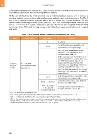
communication of vectoring feedback reports, the FTU-O shall send a vectoring feedback command that
carries a special value of VF sample update period q=0 (see Table 11-40). Upon reception of the command
containing q=0, the FTU-R shall first stop sending vectoring feedback responses and subsequently respond
with NACK.
Table 11-40 – Vectoring feedback command (transmitted by the FTU-O)
Name Length (bytes) Byte number Content
2 0116 (Note)
First CNTSF (CNTSF , see clause10.3.2.5.2)
3 to 4 0
represented as an unsigned integer
Bits [3:0]: VFRB update period (q) (see
clause 10.3.2.5.2), represented as an
unsigned integer (Note 2, 3)
Bit [4]: reporting mode: if set to 0 the VFRB
shall carry clipped error samples, if set to 1,
the VFRB shall carry both clipped error
5
Vectoring 9 + 5 N_band samples and DFT output samples (see
feedback +ceiling(Nprobe_ds/8) clause 10.3.2.4.1) using the per-element VF
reporting mode defined in Table 11-41
request (N_band 8)
Bits [7:5]: VFRB frequency shift step (s) (see
clause 10.3.2.5.1), represented as unsigned
integer (Note 4)
VFRB shift period (z) (see clause 10.3.2.5.2),
6 to 7
represented as an unsigned integer
Vectored bands formatted using the bands
8 to 8 + 3 N_band
descriptor (see Table 12-21)
9 + 3 N_band to
Vectoring feedback report configuration
9 + 5 N_band descriptor defined in Table 11-41
+ceiling(Nprobe_ds/8)
NOTE – All other values are reserved by ITU-T.
NOTE 2 – Setting the value of parameter q to 0000 2 stops the report (see clause 10.3.2.5.1 and clause 10.3.2.5.2).
NOTE 3 – For frequency identification, the value of parameter q shall be set to 0001 2.
NOTE 4 – The value of parameter s determines whether frequency identification or time identification shall be used (see clause
10.3.2.5). Setting s = 000 2 indicates time identification (see clause 10.3.2.5.2) and setting s ≠ 000 2 indicates frequency
identification (see clause 10.3.2.5.1). In the latter case value of z shall be ignored.
832