Page 843 - 5G Basics - Core Network Aspects
P. 843

Transport aspects                                              2


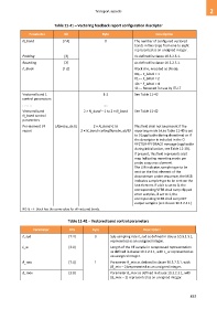
                               Table 11-41 – Vectoring feedback report configuration descriptor

                 Parameter          Bit                  Byte                          Description
             N_band                [7:4]                   0               The number of configured vectored
                                                                           bands in the range from one to eight
                                                                           represented as an unsigned integer.

             Padding                [3]                                    As defined in clause 10.3.2.3.1.
             Rounding               [2]                                    As defined in clause 10.3.2.3.1.
             F_block               [1:0]                                   Block size, encoded as (Note):
                                                                           002 – F_block = 1
                                                                           012 – F_block = 2
                                                                           102 – F_block = 4
                                                                           112 – Reserved for use by ITU-T

             Vectored band 1                              1-2              See Table 11-42
             control parameters
             . . . . . .                                  …..
             Vectored band                     2 × N_band – 1 to 2 × N_band   See Table 11-42
             N_band control
             parameters
             Per-element VF     [Nprobe_ds:0]       2 × N_band+1 to        This field shall not be present if the
             report                          2 × N_band+ceiling(Nprobe_ds/8)  reporting mode bit in Table 11-40 is set
                                                                           to 0 (applicable during showtime) or if
                                                                           the descriptor is included in the O-
                                                                           VECTOR-FEEDBACK message (applicable
                                                                           during initialization, see Table 12-28).
                                                                           If present, this field represents a bit
                                                                           map indicating reporting mode per
                                                                           probe sequence element.
                                                                           The LSB indicates sample type to be
                                                                           sent on the first element of the
                                                                           downstream probe sequence, the MSB
                                                                           indicates sample type to be sent on the
                                                                           last element. If a bit is set to 0, the
                                                                           corresponding VFRB shall carry clipped
                                                                           error samples, if set to 1, the
                                                                           corresponding VFRB shall carry DFT
                                                                           output samples (see clause 10.3.2.4.1)
             NOTE – F_block has the same value for all vectored bands.


                                      Table 11-42 – Vectored band control parameters

                   Parameter           Bits         Byte                        Description
             F_sub                     [7:4]         0        Sub-sampling rate F_sub as defined in clause 10.3.2.3.1,
                                                              represented as an unsigned integer.
             L_w                       [3:0]                  Length of the VF sample in compressed representation
                                                              as defined in clause 10.3.2.3.1, with L_w represented as
                                                              an unsigned integer.
             B_min                     [7:4]         1        Parameter B_min as defined in clause 10.3.2.3.1, with
                                                              (B_min – 2) represented as an unsigned integer.
             B_max                     [3:0]                  Parameter B_max as defined in clause 10.3.2.3.1, with
                                                              (B_max – 2) represented as an unsigned integer.


                                                                                                         833
   838   839   840   841   842   843   844   845   846   847   848