
Page 811 - 5G Basics - Core Network Aspects
P. 811
Transport aspects 2
The NMS, connected to the FTU-O via the Q interface, controls the OAM entities at both FTUs, and collects
management data from all relevant OAM entities of both FTU-O and FTU-R. The upper-layer ME provides
the interface to the NMS (Q interface), and the interface with the DPU-MIB. The DPU-MIB contains all of
the management information related to the ITU-T G.9701 link. It may be implemented to serve an
individual line or to be shared between the lines served by the DPU. In some implementations a MIB can
also be established in the NT and connected to the NMS via the G-interface (see Figure 5-1) and connected
to the ME at the FTU-O via the eoc.
The ME-O shall update and store the set of near-end test parameters or far-end test parameters or both
(the ones that can be updated during the showtime) upon the request to do so from the NMS.
11.1.1 γ_MGMT interface
The γO_MGMT and γR_MGMT reference points describe logical interfaces between the FME and the upper
layer management entity ME-O (at the FTU-O) and ME-R (at the FTU-R), respectively (see Figure 8-1,
Figure 8-2 and Figure 11-1). The interface is defined by a set of control and management parameters
(primitives). These parameters are divided into four groups:
– parameters generated by the FME and submitted to the upper-layer ME;
– parameters retrieved by the upper-layer ME from the FME (requested by the ME to be submitted
by the FME to upper-layer ME);
– parameters retrieved by the FME from the upper-layer ME. These parameters are used by the FME
to control the FTU via TPS-TC_MGMT, PMS-TC_MGMT and PMD_MGMT interfaces;
– parameters generated by the upper-layer ME and submitted to the FME to control the local FTU or
to be transported to the peer FME and submitted to the peer upper-layer ME.
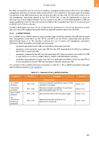
The summary of the γ_MGMT primitives is presented in Table 11-1. The γ_MGMT parameters exchanged
with the MIB are defined in [ITU-T G.997.2].
Table 11-1 – Summary of the γ_MGMT primitives
Primitive Direction Description Reference
OAM primitives
Line-related FME → ME Represent anomalies and defects related to PMD Clause 11.3.1
primitives and PMS-TC sub-layers.
Path-related Represent anomalies and defects of a particular
FME → ME Clause 11.3.2
primitives path terminated by peer TPS-TCs.
Power-related
FME → ME Represent the status of the FTU power supply. Clause 11.3.3
primitives
Line
performance FME → ME Represent parameters defined for line Clause 11.4.4
monitoring performance monitoring.
parameters
801