
Page 814 - 5G Basics - Core Network Aspects
P. 814
2 Transport aspects
Byte MSB LSB
1, 2 Control field 1
3 eoc message 1 byte 1
... ....
P1 + 2 eoc message 1 byte P1
P1 + 3, P1 + 4 Control field 2
P1 + 5 eoc message 2 byte 1
... ....
P2 + P1 + 4 eoc message 2 byte P2
……….
Control field m
... eoc message m byte 1
... ....
P − 2 eoc message m byte Pm
P − 1 FCS high byte
P FCS low byte
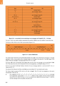
Figure 11-2 – eoc packet format containing m eoc messages with length P1, P2, … Pm bytes
The byte 1 of the eoc packet shall be transmitted first and the MSB of each byte shall be transmitted first.
The format of the 16-bit control field is presented in Figure 11-3.
MSB LSB
Control field byte 1 Control field byte 2
15 14 13 12 11 10 09 08 07 06 05 04 03 02 01 00
Length C/R Priority
Figure 11-3 – Control field format
The 10-bit length field of the control field shall indicate the length of the following eoc message or message
segment in bytes, represented as the unsigned integer in the length field plus one. The valid range of the
length of the eoc message or message segment is from 2 to 1 020.
The three LSBs of the control field shall indicate the priority of the eoc message sent as specified in Table
11-2. The value of priority shall correspond to the eoc message type, as defined in clause 11.2.2.2.
Bit 03 of the control field shall indicate whether the eoc message contains a command (C/R = 0) or a
response (C/R = 1).
The values of bits 15 and 14 of the control field are reserved by ITU-T and shall be set to zero.
The frame check sequence (FCS) shall be 16 bits in length. The FCS shall be computed as the one's
complement of the sum of:
10
9
12
11
6
5
8
7
13
15
14
k
2
3
4
a) the remainder of x (x + x + x + x + x + x + x + x + x + x + x + x + x + x + x + 1) divided
12
16
5
by the generator polynomial x + x + x + 1, where k is the number of bits in the eoc packet
counted from the LSB of the byte 1 of the eoc packet to the MSB of the last byte (byte P – 2) of the
last eoc message in the eoc packet, inclusive; and
804