
Page 705 - 5G Basics - Core Network Aspects
P. 705
Transport aspects 2
NOTE – The values PSD1 and PSD2 of the LESM are the only allowed breakpoints in the MIBPSDMASK outside of the
[0, −90] dBm/Hz range.
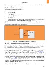
7.3.1.1.2.2.1 One-slope steep upward shape
The one-slope steep upward shape is defined as:
• PSD3 = –80 dBm/Hz;
• PSD4 −65 dBm/Hz;
PSD PSD 3 . 2 86 dB / 51.75 kHz
4
t t
• 4 3
• PSDj PSD4 for all j > 4;
• breakpoints (t5, PSD5), ..., (tn, PSDn), ..., (tNBP, PSDNBP) shall also be according to the requirements for
the breakpoints for the regular PSD shaping as defined in clause 7.3.1.1.2.1.
NOTE – These slopes correspond approximately to a maximum of 15 dB increase in the PSD mask level over six
subcarriers.
The one-slope steep upward shape is illustrated in Figure 7-3.
PSD in
dBm/Hz
MIBPSDMASK
PSD ≤ −65
4
PSD ≤ PSD
j 4
−80 PSD≤ 3 ≤ −65
Slope ≤
2.86 dB/51.75 kHz
t 3 t 4 G.9701(14) _F7- 3
Figure 7-3 – Illustration of the one-slope steep upward shape
7.3.1.1.2.3 Definition of breakpoints at the edge of a band
Except for the specification of the LESM, no additional restrictions on the MIBPSDMASK are imposed at the
band edges. The values PSD1 and PSDNBP can be any value between the value of the LPM at that frequency
and −90 dBm/Hz, provided that the MIBPSDMASK construction rules are not violated as a result.
7.3.1.2 Notching of specific frequency bands
The ITU-T G.9701 transmitters shall be able to notch one or more specific frequency bands in order to
protect radio services, for example, international amateur radio bands (see Appendix I of [ITU-T G.9700]) or
broadcast radio bands. In this Recommendation, the international amateur radio bands to be notched are
referred to as IAR bands, whilst the rest of the bands to be notched are referred to as RFI bands
(parameters IARBANDS and RFIBANDS, respectively, in Table 7-3).
The required PSD level in the notched frequency bands (TXPSDM_N and TXPSDM_W) shall be as specified
in clause 6.5 of [ITU-T G.9700]. Within notched frequency bands, all subcarriers shall be turned off
(see clause 6.5 of [ITU-T G.9700]), i.e., Zi' = 0 (see Figure 10-16).
The value of TXPSDM_N shall be accounted for in the determination of all U-interface transmit PSD masks
(see Figure 7-1 and Table 7-1 through Table 7-3).
An FTU shall support notching of 32 RFI bands and notching of 12 IAR bands simultaneously.
695