
Page 710 - 5G Basics - Core Network Aspects
P. 710
2 Transport aspects
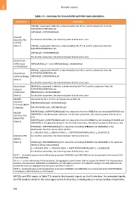
Table 7-2 – Formulae for transmit PSD and PSD mask calculations
Parameter Calculation
CDPSDds, expressed in dBm/Hz, is determined by the FTU-O, and for subcarriers from the
SUPPORTEDCARRIERSds set:
CDPSDds(f) ≤ CDPSDMASKds(f)
Channel
discovery PSD For all other subcarriers, the transmit power shall be set to zero
(CDPSD)
(Note 2) CDPSDus, expressed in dBm/Hz, is determined by the FTU-R, and for subcarriers from the
SUPPORTEDCARRIERSus set:
CDPSDus(f) ≤ CDPSDMASKus(f)
For all other subcarriers, the transmit power shall be set to zero.
Downstream
V2PSD mask V2PSDMASKds (f) = min[CDPSDMASKds(f) , MAXMASKds]
(V2PSDMASKds)
V2PSDds, expressed in dBm/Hz, is determined by the FTU-O, and for subcarriers from the
Downstream SUPPORTEDCARRIERSds set:
V2PSD (V2PSDds) V2PSDds(f) ≤ V2PSDMASKds (f)
(Note 2)
For all other subcarriers, the transmit power shall be set to zero
Downstream PRMPSDds, expressed in dBm/Hz, is determined by the FTU-O and for subcarriers from the
PRMPSD SUPPORTEDCARRIERSds set:
(PRMPSDds) PRMPSDds(f) ≤ V2PSDMASKds(f)
(Note 2) For all other subcarriers, the transmit power shall be set to zero
MEDLEY Calculated by the FTU-O for all frequencies as (Note 3):
reference MREFPSDMASKds(f)= V2PSDMASKds(f)
PSD mask (MREF
PSDMASK) MREFPSDMASKus(f)= CDPSDMASKus(f)
MREFPSDds(f) ≤ (MREFPSDMASKds(f) ) for subcarriers from the MEDLEYds set (including RFIBANDS and
MEDLEY
IARBANDS) in the downstream direction. For all other subcarriers, the transmit power shall be set to
reference PSD
(MREFPSD) zero.
MREFPSDus(f) ≤ (MREFPSDMASKus(f) ) for subcarriers from the MEDLEYus set (including RFIBANDS and
(Note 2)
IARBANDS) in the upstream direction. For all other subcarriers, the transmit power shall be set to zero.
STPSDds(f) ≤ MREFPSDMASKds(f) for subcarriers (including RFIBANDS and IARBANDS) in the
downstream direction whose index satisfies:
(i MEDLEY) OR [(i MEDLEY) AND (i SUPPORTEDCARRIERS) AND (i BLACKOUT)].
Showtime PSD For all other subcarriers, the transmit power shall be set to zero.
(STPSD)
(Note 2) STPSDus(f) ≤ MREFPSDMASKus(f) for subcarriers (including RFIBANDS and IARBANDS) in the upstream
direction whose index satisfies:
(i MEDLEY) OR [( i MEDLEY) AND (i SUPPORTEDCARRIERS) AND (i BLACKOUT)].
For all other subcarriers, the transmit power shall be set to zero.
NOTE 1 – Notched frequency bands (defined by parameters RFIBANDS and IARBANDS) are not incorporated in the transmit PSD
mask (PSDMASK).
NOTE 2 – For any valid setting of this parameter, the aggregate transmit power shall not exceed the MAXATP for the associated
direction of transmission. MAXATPds and MAXATPus are DPU-MIB parameters. The MAXATP settings in the DPU-MIB shall not
exceed the maximum aggregate transmit power specified in Table 6-1.
NOTE 3 – Notched frequency bands (defined by parameters RFIBANDS and IARBANDS) are incorporated in the STARTPSDMASK,
CDPSDMASK, MREFPSDMASK and STPSDMASK.
All PSDs and PSD masks in Table 7-2 relate to the transmit signals on the U-interface. For precoded signals,
the PSD mask is a limit for the total signal on the U-interface, including the pre-compensation components.
700