
Page 702 - 5G Basics - Core Network Aspects
P. 702
2 Transport aspects
An FTU shall always confine the PSD of its transmit signal to be within the final transmit PSD masks
(U-interface transmit PSD masks) shown in Figure 7-1. By construction, all U-interface transmit PSD masks
are below the TxPSDM, which is determined by [ITU-T G.9700] parameters listed above.
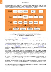
Figure 7-1 – Relation between ITU-T G.9700 PSD masking functions,
DPU-MIB configuration parameters, ITU-T G.9701 transceiver control parameters
and final transmit PSD mask (at U-interface)
The limit PSD mask (LPM) specified in [ITU-T G.9700] is referred to in the DPU-MIB and in this
Recommendation as LIMITMASK.
A PSD shaping mask (PSM) may be specified by the service provider and is provided to the FTU-O via the
DPU-MIB parameter MIBPSDMASK.
If a low-frequency edge stop-band mask (LESM) is configured such that ftr3 > ftr1 (see Figures 6-1 and 7-1 of
[ITU-T G.9700]), the DPU-MIB parameter MIBPSDMASK shall also be used to specify the part of the LESM
above ftr1, consistent with [ITU-T G.9700]. The part of the LESM below ftr1 is specified in [ITU-T G.9700].
Both the LIMITMASK and the MIBPSDMASK are translated into a ITU-T G.9701 control parameter PSDMASK
(PSDMASKds and PSDMASKus for downstream and upstream, respectively).
In the upstream direction, upstream power back off (UPBO) provides further PSD reduction to improve
spectral compatibility between ITU-T G.9701 transceivers operating on loops of different lengths deployed
in the same binder. It is an autonomous PSD reduction implemented within constraints configured via the
DPU-MIB parameters UPBOPSD, UPBOKLREF, UPBOKLF and UPBOKL which results in an additional
upstream mask defined by the ITU-T G.9701 control parameter UPBOMASK.
The notching of specific frequency bands is configured via the DPU-MIB parameters RFIBANDS and
IARBANDS, and is controlled in an ITU-T G.9701 transceiver via the parameters RFIBANDS and IARBANDS,
respectively (same for both transmission directions).
The subcarrier masking function is configured via the DPU-MIB parameter CARMASK, and is controlled in an
ITU-T G.9701 FTU via the parameters SUPPORTEDCARRIERSus and SUPPORTEDCARRIERSds for upstream
and downstream, respectively.
The ITU-T G.9701 control parameter MAXMASK (as specified in clause 12.3.3) allows the transceivers to
autonomously reduce further the transmit PSD mask.
692