
Page 356 - 5G Basics - Core Network Aspects
P. 356
1 Core network aspects
The configuration makes alignment between the resource IDs at the MUE and the network. Additionally, a
new interface between the MUE and the network is required to be defined as well as the functional
description of the configuration.
7.1 Relations between resource identifiers within each layer
This clause describes the relations between the resource IDs by using a layering point of view in order to
provide information for configuration as well as to describe its mapping. The abstraction points may be
represented by mapping of the resource IDs as described in Figure 7-1. Basically there are several possible
relations between the upper abstraction point (UAP) and the lower abstraction point (LAP), such as one-to-
one, N-to-one, and N-to-N mapping to represent different configurations among the resource IDs at the MUE.
Therefore, all of the resource IDs at the MUE are required to be mapped for configuration by various mapping
types such that one UAP can be split into multiple LAPs and multiple UAPs can be merged to one LAP.
A. One to one mapping B. N to one mapping C. N to N mapping
Upper ID Upper ID(s) Upper ID(s)
Upper abstraction point
(UAP)
...
Lower abstraction point
(LAP)
Lower ID Lower ID Lower ID(s)
Abstraction point Relationship Y.2252(12)_F7-1
Figure 7-1 – Conceptual configuration of multi-connection IDs in the MUE
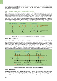
7.1.1 MAC and PHY layer
In the MAC and PHY layer, each upper abstract point (UAP) is represented by the interface ID (IFID) like MAC
address, and each lower abstraction point (LAP) is represented by the access network ID (ANID) given from
the multi-connection network. Multiple IFIDs may attach just one access network so that multiple IFIDs are
mapped to one ANID as shown in case A of Figure 7-2. Some LAPs may be a set of multiple access networks
so that there is a mapping between multiple ANIDs and multiple IFIDs as shown in case B of Figure 7-2. As
shown in case C in Figure 7-2, multiple IFIDs may be represented by one logical/virtual IFID in order to be
easily configured so that multiple ANIDs representing the LAP may be mapped to one logical/virtual IFID.
A. Same ANID and B. Different ANIDs C. Logical interface
different IFIDs and IFIDs
Interface IDs Interface IDs Interface IDs
#1 #2 #3 #1 #2 #3 #1 #2 #3
UAP
Virtual
MAC/PHY interface ID
layer
LAP
#1 #2 #3 #1 #2 #3
Access network ID Access network IDs Access network IDs
Abstraction point Relationship Y.2252(12)_F7-2
Figure 7-2 – Configuration of interface IDs and access network IDs
7.1.2 Network layer
In the network layer, each UAP is generally represented by IP flow ID (FLID), which can be substituted by one
or more IP addresses. In case A shown in Figure 7-3, an FLID may generally be mapped to an IFID as one-to-
one mapping. As shown in cases B and C in Figure 7-3, multiple FLIDs may be configured with one IFID, or an
346