
Page 1207 - 5G Basics - Core Network Aspects
P. 1207
Transport aspects 2
MFAS 1 2 3 4 5 6 7 8 238 MFAS 1 2 3 4 5 6 7 8 238
bits bits
5678 1 45678 1
2 2
0000 00000
3 3
4 4
ODTU13 ... ODTU13 ...
1 1
2 2
1111 11111
3 3
4 4
OPU3 1.25G TS #A OPU3 1.25G TS #B
OPU3 2.5G TS #i
1 1 1
2 00000 2 2
0000
3 3 3
4 4 4
... ... ...
1 1 1
2 2 2
1111 11111
Column 16 3 Column 16 3 3
OPU3
TSOH 4 OPU3 4 4
of TS #i 1 2 238 TSOH 1 2 119 1 2 119
of TS #A,
#B
G.709-Y.1331(12)_F19-8
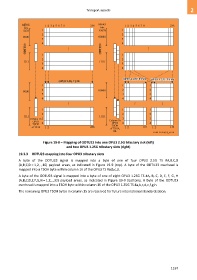
Figure 19-8 – Mapping of ODTU13 into one OPU3 2.5G tributary slot (left)
and two OPU3 1.25G tributary slots (right)
19.3.3 ODTU23 mapping into four OPU3 tributary slots
A byte of the ODTU23 signal is mapped into a byte of one of four OPU3 2.5G TS #A,B,C,D
(A,B,C,D = 1,2,..,16) payload areas, as indicated in Figure 19-9 (top). A byte of the ODTU23 overhead is
mapped into a TSOH byte within column 16 of the OPU3 TS #a,b,c,d.
A byte of the ODTU23 signal is mapped into a byte of one of eight OPU3 1.25G TS #A, B, C, D, E, F, G, H
(A,B,C,D,E,F,G,H = 1,2,..,32) payload areas, as indicated in Figure 19-9 (bottom). A byte of the ODTU23
overhead is mapped into a TSOH byte within column 16 of the OPU3 1.25G TS #a,b,c,d,e,f,g,h.
The remaining OPU3 TSOH bytes in column 15 are reserved for future international standardization.
1197