
Page 1212 - 5G Basics - Core Network Aspects
P. 1212
2 Transport aspects
1 2 3 ... ts 95 ts
1,2 1
3,4 2
1,2 3
3,4 4
ODTU4.ts
JC4 JC1 JC5 JC2 1,2 157
158
3,4
JC6 JC3
1,2 159
3,4 160
OMFI
bits
2345678 TS #A OPU4 TS #A OPU4 TS #B OPU4 TS #X
RES RES RES RES 3 4 3 4 3 4
0000000 RES RES 1 2 1 2 1 2
OPU4 tributary slots TS #B RES RES
1001111 RES RES RES RES TS #X 1 2 1 2 1 2
3 4 3 4 3 4
OPU4 TSOH JC4 JC1 JC5 JC2
of TS #a, b, ..., x 1 2 47/ 48/ 95 1 2 47/ 48/ 95 1 2 47/ 48/ 95
JC6 JC3 48 49 48 49 48 49
G.709-Y.1331(12)_F19-13
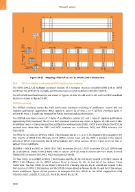
Figure 19-13 – Mapping of ODTU4.ts into 'ts' OPU4 1.25G tributary slots
19.4 OPUk multiplex overhead and ODTU justification overhead
The OPUk (k=1,2,3,4) multiplex overhead consists of a multiplex structure identifier (MSI) and an ODTU
overhead. The OPUk (k=4) multiplex overhead contains an OPU multiframe identifier (OMFI).
The OPUk MSI overhead locations are shown in Figures 19-14A, 19-14B and 19-14C and the OMFI overhead
location is shown in Figure 19-14C.
ODTUjk overhead
The ODTUjk overhead carries the AMP justification overhead consisting of justification control (JC) and
negative justification opportunity (NJO) signals in column 16 of rows 1 to 4. ODTUjk overhead bytes in
column 15 rows 1, 2 and 3 are reserved for future international standardization.
The ODTUjk overhead consists of 3 bytes of justification control (JC) and 1 byte of negative justification
opportunity (NJO) overhead. The JC and NJO overhead locations are shown in Figures 19-14A and 19-14B.
In addition, two or n times two positive justification overhead bytes (PJO1, PJO2) are located in the ODTUjk
payload area. Note that the PJO1 and PJO2 locations are multiframe, ODUj and OPUk tributary slot
dependent.
The PJO1 for an ODU1 in OPU2 or OPU3 2.5G tributary slot #i (i: 1..4 or 1..16 respectively) is located in the
first column of OPUk 2.5G tributary slot #i (OPUk column 16+i) and the PJO2 is located in the second
column of OPUk 2.5G tributary slot #i (OPU2 column 20+i, OPU3 column 32+i) in frame #i of the four or
sixteen frame multiframe.
EXAMPLE – ODU1 in OPU2 or OPU3 TS(1): PJO1 in column 16+1=17, PJO2 in column 20+1=21 (OPU2) and
32+1=33 (OPU3). ODU1 in OPU2 TS(4): PJO1 in column 16+4=20, PJO2 in column 20+4=24. ODU1 in OPU3
TS(16): PJO1 in column 16+16=32, PJO2 in column 32+16=48.
The four PJO1s for an ODU2 in OPU3 2.5G tributary slots #a, #b, #c and #d are located in the first column of
OPU3 2.5G tributary slot #a (OPU3 column 16+a) in frames #a, #b, #c and #d of the sixteen frame
multiframe. The four PJO2s for an ODU2 in OPU3 2.5G tributary slots #a, #b, #c and #d are located in the
first column of OPU3 2.5G tributary slot #b (OPU3 column 16+b) in frames #a, #b, #c and #d of the sixteen
frame multiframe. Figure 19-14A presents an example with four ODU2s in the OPU3 mapped into 2.5G
tributary slots (1,5,9,10), (2,3,11,12), (4,14,15,16) and (6,7,8,13).
1202