Page 1206 - 5G Basics - Core Network Aspects
P. 1206

2                                                 Transport aspects


            The OPUk overhead for these multiplexed signals consists of a payload type (PT), the multiplex structure
            identifier (MSI), the OPU4 multiframe identifier (k=4), the OPUk tributary slot overhead carrying the ODTU
            overhead  and  depending  on  the  ODTU  type  one  or  more  bytes  reserved  for  future  international
            standardization.

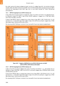
            19.3.1  ODTU12 mapping into one OPU2 tributary slot

            A byte of the ODTU12 payload signal is mapped into a byte of an OPU2 2.5G TS #i (i = 1,2,3,4) payload area,
            as  indicated  in  Figure  19-7  (left).  A  byte  of  the  ODTU12  overhead  is  mapped  into  a  TSOH  byte  within
            column 16 of the OPU2 2.5G TS #i.
            A  byte  of  the  ODTU12  signal  is  mapped  into  a  byte  of  one  of  two  OPU2  1.25G  TS  #A,B  (A,B = 1,2,..,8)
            payload areas, as indicated in Figure 19-7 (right). A byte of the ODTU12 overhead is mapped into a TSOH
            byte within column 16 of the OPU2 1.25G TS #a,b.
            The remaining OPU2 TSOH bytes in column 15 are reserved for future international standardization.


               MFAS         1 2 3 4 5 6 7 8             952  MFAS           1 2 3 4 5 6 7 8             952
                bits                                          bits
                78         1                                  678          1
                           2                                               2
                 00                                           000
                           3                                               3
                           4                                               4
                 ODTU12                    ...                ODTU12                       ...

                           1                                               1
                           2                                               2
                 11                                            111
                           3                                               3
                           4                                               4


                                                                           OPU2 1.25G TS #A  OPU2 1.25G TS #B
                                     OPU2 2.5G TS #i
                           1                                               1               1
                           2                                  000          2               2
                 00
                           3                                               3               3
                           4                                               4               4
                                           ...                                     ...             ...

                           1                                               1               1
                           2                                               2               2
                 11                                            111
                    Column 16  3                                   Column 16  3            3
                     OPU2  4                                               4               4
                     TSOH                                            OPU2
                    of TS #i  1 2                       952         TSOH    1 2        476   1 2        476
                                                                    of TS #A,
                                                                      #B
                                                                                             G.709-Y.1331(12)_F19-7

                           Figure 19-7 – Mapping of ODTU12 into one OPU2 2.5G tributary slot (left)
                                         and two OPU2 1.25G tributary slots (right)

            19.3.2  ODTU13 mapping into one OPU3 tributary slot

            A byte of the ODTU13 signal is mapped into a byte of an OPU3 2.5G TS #i (i = 1,2,..,16) payload area, as
            indicated in Figure 19-8 (left). A byte of the ODTU13 overhead is mapped into a TSOH byte within column
            16 of the OPU3 2.5G TS #i.
            A byte of the ODTU13 signal is mapped into a byte of one of two OPU3 1.25G TS #A, B (A,B = 1,2,..,32)
            payload areas, as indicated in Figure 19-8 (right). A byte of the ODTU13 overhead is mapped into a TSOH
            byte within column 16 of the OPU3 1.25G TS #a,b.
            The remaining OPU3 TSOH bytes in column 15 are reserved for future international standardization.


            1196
   1201   1202   1203   1204   1205   1206   1207   1208   1209   1210   1211