Page 1147 - 5G Basics - Core Network Aspects
P. 1147
Transport aspects                                              2


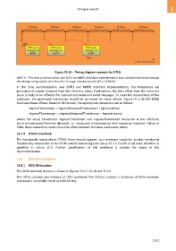
                                      Figure 15-16 – Timing diagram example for OTUk
            NOTE 3 – This time synchronization over SOTU and MOTU interface implementation does not generate event message
            timestamps using a point other than the message timestamp point [ITU-T G.8260].
            In  this  time  synchronization  over  SOTU  and  MOTU  interface  implementation,  the  timestamps  are
            generated at a point removed from the reference plane. Furthermore, the time offset from the reference
            plane is likely to be different for inbound and outbound event messages. To meet the requirement of this
            subclause,  the  generated  timestamps  should  be  corrected  for  these  offsets.  Figure 19  in  [b-IEEE 1588]
            illustrates these offsets. Based on this model, the appropriate corrections are as follows:

                    <egressTimestamp> = <egressMeasuredTimestamp> + egressLatency
                    <ingressTimestamp> = <ingressMeasuredTimestamp> ─ ingressLatency
            where  the  actual  timestamps  <egressTimestamp>  and  <ingressTimestamp>  measured  at  the  reference
            plane are computed from the detected, i.e., measured, timestamps by their respective latencies. Failure to
            make these corrections results in a time offset between the slave and master clocks.
            15.7.3  OTUkV overhead

            The functionally standardized OTUkV frame should support, as a minimum capability, section monitoring
            functionality comparable to the OTUk section monitoring (see clause 15.7.2.1) with a trail trace identifier as
            specified  in  clause  15.2.  Further  specification  of  this  overhead  is  outside  the  scope  of  this
            Recommendation.

            15.8    ODU OH description

            15.8.1  ODU OH location
            The ODU overhead location is shown in Figures 15-17, 15-18 and 15-19.

            The ODUk contains one instance of ODU overhead. The  ODUCn contains n instances of ODU overhead,
            numbered 1 to n (ODU OH #1 to ODU OH #n).


                                                                                                        1137

