
Page 1142 - 5G Basics - Core Network Aspects
P. 1142
2 Transport aspects
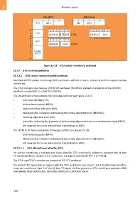
Figure 15-13 OTU section monitoring overhead
15.7.2 OTU overhead definition
15.7.2.1 OTU section monitoring (SM) overhead
One field of OTU section monitoring (SM) overhead is defined in row 1, columns 8 to 10 to support section
monitoring.
The OTUk contains one instance of OTU SM overhead. The OTUCn contains n instances of the OTU SM
overhead, numbered 1 to n (SM #1 to SM #n).
The SM and SM #1 field contains the following subfields (see Figure 15-13):
trail trace identifier (TTI);
bit interleaved parity (BIP-8);
backward defect indication (BDI);
backward error indication and backward incoming alignment error (BEI/BIAE);
incoming alignment error (IAE);
status bits indicating the presence of an incoming alignment error or a maintenance signal (STAT);
bits reserved for future international standardization (RES).
The SM #2 to #n fields contain the following subfields (see Figure 15-13):
bit interleaved parity (BIP-8);
backward error indication and backward incoming alignment error (BEI/BIAE);
bits reserved for future international standardization (RES).
15.7.2.1.1 OTU SM trail trace identifier (TTI)
For section monitoring, a one-byte trail trace identifier (TTI) overhead is defined to transport the 64-byte
TTI signal specified in clause 15.2 or a discovery message as specified in [ITU-T G.7714.1].
The OTUk and OTUCn contain one instance of OTU TTI overhead.
The 64-byte TTI signal shall be aligned with the OTU multiframe (see clause 15.6.2.2) and transmitted four
times per multiframe. Byte 0 of the 64-byte TTI signal shall be present at OTU multiframe positions 0000
0000 (0x00), 0100 0000 (0x40), 1000 0000 (0x80) and 1100 0000 (0xC0).
1132