
Page 1145 - 5G Basics - Core Network Aspects
P. 1145
Transport aspects 2
Table 15-2 OTUCn SM status interpretation
SM byte 3
Status
bits 6 7 8
0 0 0 Reserved for future international standardization
0 0 1 In use without IAE
0 1 0 In use with IAE
0 1 1 Reserved for future international standardization
1 0 0 Reserved for future international standardization
1 0 1 Reserved for future international standardization
1 1 0 Reserved for future international standardization
1 1 1 Maintenance signal: OTUCn-AIS
A S-CMEP ingress point sets these bits to either "001" to indicate to its peer S-CMEP egress point that there
is no incoming alignment error (IAE), or to "010" to indicate that there is an incoming alignment error.
The S-CMEP egress point may use this information to suppress the counting of bit errors, which may occur
as a result of a frame phase change of the ODUCn at the ingress of the section.
15.7.2.2 OTU general communication channel 0 (GCC0)
Two bytes are allocated in the OTU overhead to support a general communications channel or a discovery
channel as specified in [ITU-T G.7714.1] between OTU termination points.
This general communication channel is a clear channel and any format specification is outside of the scope
of this Recommendation. These bytes are located in row 1, columns 11 and 12 of the OTU overhead.
The OTUk contains one instance of OTU GCC0 overhead. The OTUCn contains n instances of the OTU GCC0
overhead, numbered 1 to n (GCC0 #1 to GCC0 #n).
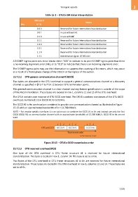
The GCC0 #1 to #n overhead are combined to provide one communication channel as illustrated in Figure
15-15 with an approximated bandwidth of n × 13.768 Mbit/s.
NOTE – For vendor specific interfaces it is an option not to combine the GCC0 #1 to #n and instead use only the first
GCC0 (GCC0 #1) as communication channel with an approximate bandwidth of 13.768 Mbit/s. GCC0 #2 to #n are not
used.
Figure 15-15 – OTUCn GCC0 transmission order
15.7.2.3 OTU reserved overhead (RES)
One byte of the OTU overhead in OTU frame structure #1 is reserved for future international
standardization. This byte is located in row 1, column 14. This byte is set to all-0s.
Two bytes of the OTU overhead in OTU frame structures #2 to #n are reserved for future international
standardization. These bytes are located in the OTU overhead in row 1, columns 13 and 14. These bytes are
set to all-0s.
1135