
Page 1117 - 5G Basics - Core Network Aspects
P. 1117
Transport aspects 2
Figure 7-3 presents the multiplexing of up to 16 ODU1 signals and/or up to 4 ODU2 signals into the OPU3
signal via the ODTUG3 (PT=20). An ODU1 signal is extended with a frame alignment overhead and
asynchronously mapped into the optical data tributary unit 1 into 3 (ODTU13) using the AMP justification
overhead (JOH). An ODU2 signal is extended with a frame alignment overhead and asynchronously mapped
into the optical data tributary unit 2 into 3 (ODTU23) using the AMP justification overhead (JOH). "x"
ODTU23 (0 x 4) signals and "16-4x" ODTU13 signals are time-division multiplexed into the optical data
tributary unit group 3 (ODTUG3) with payload type 20, after which this signal is mapped into the OPU3.
ODU2 ODU1
OH ODU2 payload ODU2 OH ODU1 payload ODU1
ODTU23 ODU2 ODTU23 ODTU13 ODU1 ODTU13
JOH JOH
ODTU13 ... ODTU13 ODTU23 .... ODTU23 ODU2 ...... ODU2 ODU1 ... ODU1 ODTUG3
JOH JOH JOH JOH
ODTUG3
OPU3 OPU3 payload
OH OPU3
ODU3 ODU3 payload
OH ODU3
G.709-Y.1331(12)_F7-3
Figure 7-3 ODU1 and ODU2 into ODU3 multiplexing method via ODTUG3 (PT=20)
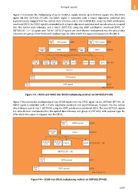
Figure 7-4 presents the multiplexing of two ODU0 signals into the OPU1 signal via the ODTUG1 (PT=20). An
ODU0 signal is extended with a frame alignment overhead and asynchronously mapped into the optical
data tributary unit 0 into 1 (ODTU01) using the AMP justification overhead (JOH). The two ODTU01 signals
are time-division multiplexed into the optical data tributary unit group 1 (ODTUG1) with payload type 20,
after which this signal is mapped into the OPU1.
ODU0 ODU0 payload ODU0
OH
ODTU01 ODU0 ODTU01
JOH
ODTU01 ODTU01 ODU0 ODU0 ODTUG1 (PT = 20)
JOH JOH
ODTUG1 (PT = 20)
OPU1 OPU1 payload OPU1
OH
ODU1 ODU1 payload ODU1
OH
G.709-Y.1331(12)_F7-4
Figure 7-4 ODU0 into ODU1 multiplexing method via ODTUG1 (PT=20)
1107