
Page 1122 - 5G Basics - Core Network Aspects
P. 1122
2 Transport aspects
8.4 Multi-OTU with management (MOTUm) interface
The MOTUm interface supports n (n ≥ 1) OTUs on n OTSiG and non-associated overhead carried by an OSC
or other means. 3R regeneration is not required at the interface.
NOTE – The OTSiG carrying an OTUk is referred to in other clauses as an OCh-P.
Vendor specific application identifiers of the OTSi or OTSiG carrying these OTUs are outside the scope of
this Recommendation.
9 Media Element
A description of the media element will be provided in [ITU-T G.872].
10 OCh and OTSiA
The OCh and OTSiA transport a digital client signal between 3R regeneration points. The OCh and OTSiA
client signals defined in this Recommendation are the OTUk, OTUk-v, OTUkV and OTUCn signals.
10.1 OCh
The OCh structure is conceptually shown in Figure 10-1. The OCh contains two parts: an overhead part
(OCh-O) and a payload part (OCh-P).
Figure 10-1 OCh information structure
10.2 Optical tributary signal assembly (OTSiA)
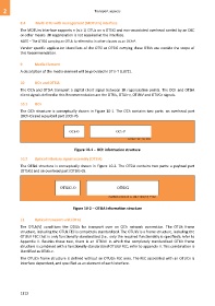
The OTSiA structure is conceptually shown in Figure 10-2. The OTSiA contains two parts: a payload part
(OTSiG) and an overhead part (OTSiG-O).
OTSiG-O OTSiG
modified version of G.709-Y.1331(12)_F10-1
Figure 10-2 OTSiA information structure
11 Optical transport unit (OTU)
The OTUk[V] conditions the ODUk for transport over an OCh network connection. The OTUk frame
structure, including the OTUk FEC is completely standardized. The OTUkV is a frame structure, including the
OTUkV FEC that is only functionally standardized (i.e., only the required functionality is specified); refer to
Appendix II. Besides these two, there is an OTUkV in which the completely standardized OTUk frame
structure is combined with a functionally standardized OTUkV FEC; refer to appendix II. This combination is
identified as OTUk-v.
The OTUCn frame structure is defined without an OTUCn FEC area. The FEC associated with an OTUCn is
interface dependent, and specified as an element of each interface.
1112