
Page 88 - ITU Kaleidoscope 2016
P. 88
MCF in terms of Λ, and we can use a Λ value of 30-40 µm
if we set -30 dB/100km as the allowable crosstalk level.
Here, it should be noted that an MCF becomes meaningless
in terms of an SDM medium if the core pitch Λ is larger
than 2×t. This is because Λ = 2t is equivalent to bundled
thin cladding fibre. However, the previous discussion makes
it clear that we can obtain sufficient SDM efficiency with a
well-designed MCF since the minimum Λ is expected to be
satisfactorily smaller than 2×t as shown by the schematic
on the right in Fig. 4.
Figure 7 shows the numerical relationship between the
number of cores and the cladding diameter D. On the basis
of the above discussion, we assumed that the Λ and t values Figure 8. Schematic relationship between
were both 35 µm. The red and blue circles show the results considerable application area of MCF and its spreading
we obtained when we used a square lattice and a hexagonal time.
core arrangement, respectively, as shown by the inset
schematic. The value in brackets shows the number of cores.
Two orange symbols also show the results when we
assumed an eight-core fibre using the modified square
lattice or circular core arrangements. Figure 7 confirms that
the cores in the MCF can be increased by using a larger D
value. However, we also found that a 37-core MCF with a
hexagonal core arrangement may require additional care as
regards mechanical reliability because the D value exceeds
250 µm. As a result, we confirmed that MCF can potentially
provide a few tens of cores for SDM transmission if we
optimise three key geometrical parameters simultaneously.
4. STANDARDIZATOIN OF MCF TECHNOLOGY
4.1. Example Milestone in MCF Technology
In this section, we investigate an example milestone in MCF
technology taking two aspects into account, namely Figure 9. Example relationship between MCF
widespread use and consistency to the current fibre design and fabrication technology.
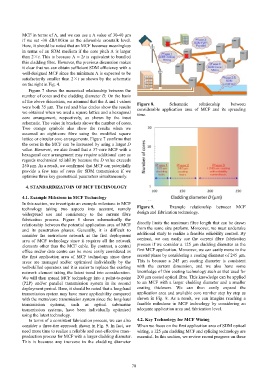
fabrication process. Figure 8 shows schematically the
relationship between the potential application area of MCF directly limits the maximum fibre length that can be drawn
and its penetration phases. Generally, it is difficult to from the same size preform. Moreover, we must undertake
consider the metro/core network as the first deployment additional study to realize a feasible reliability control. By
area of MCF technology since it requires all the network contrast, we can easily use the current fibre fabrication
elements other than the MCF cable. By contrast, a central process if we consider a 125 µm cladding diameter as the
office and/or data centre can be more easily considered as first MCF application. Moreover, we can easily move to the
the first application area of MCF technology since these second phase by considering a coating diameter of 245 µm.
areas are managed and/or optimised individually by the This is because a 245 µm coating diameter is consistent
well-skilled operators and it is easier to replace the existing with the current dimension, and we also have some
network element taking the latest trend into consideration. knowledge of thin coating technology such as that used for
We will then spread MCF technology into a point-to-point 200 µm coated optical fibre. This knowledge can be applied
(P2P) and/or parallel transmission system in its second to an MCF with a larger cladding diameter and a smaller
deployment period. Here, it should be noted that a long-haul coating thickness. We can then easily expand the
transmission system may have more applicability compared application area and available core number step by step as
with the metro/core transmission system since the long-haul shown in Fig. 9. As a result, we can imagine reaching a
transmission systems, such as optical submarine feasible milestone in MCF technology by considering an
transmission systems, have been individually optimised adequate application area and fabrication level.
using the latest technology.
In terms of a consistent fabrication process, we can also 4.2. Key Technology for MCF Wiring
consider a three-tier approach shown in Fig. 9. In fact, we When we focus on the first application area of SDM optical
need more time to realize a reliable and cost-effective mass- wiring, a 125 µm cladding MCF and splicing technology are
production process for MCF with a larger cladding diameter. essential. In this section, we review recent progress on these
This is because any increase in the cladding diameter
– 70 –