
Page 133 - Kaleidoscope Academic Conference Proceedings 2024
P. 133
Innovation and Digital Transformation for a Sustainable World
INCA functions INCA functions
Interfaces Interfaces
Control Monitoring Control Monitoring
INCA functions parameters data parameters data
Interfaces
Data network Interface NTN Interface
Control Monitoring DN controller NTN controller
parameters data Control data Control data
store store Control commands
5GC (Central)
Interface
OSM NTN simulator
5GC controller Control data Monitoring
store data collection Control commands
OpenStack NTN emulator
5GC network (VMs and networks) (Data plane path with bandwidth,
functions latency, loss rate reconfiguration)
(a) 5GC controller (b) Data network controller (c) NTN controller
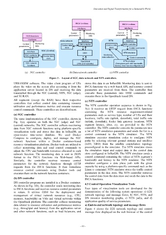
Figure 3 - Layout of 5GC, data network and NTN controllers.
UERANSIM software. The video client program of UEs stores this data in an InfluxDB. Monitoring data is sent to
plays the video on the screen after accessing it from the INCA functions via a web-based API, and resource control
application server located in DN and receiving the data parameters are received from them. The controller then
transmitted through the 5GC (central), NTN, 5GC (edge), converts these parameters into OSM commands and
and 5G RAN. executes them in the OpenStack-based DN.
All segments (except the RAN) have their respective (c) NTN controller
controllers that collect control data containing resource
utilization and performance metrics and execute resource The NTN controller operation sequence is shown in Fig.
control commands. These controllers are described next. 3(c). It receives an HTTP request from INCA functions
containing the NTN resource requirement-related
(a) 5GC controller parameters such as service type, number of UEs and their
The same implementation of the 5GC controller, shown in locations, traffic rate (uplink, downlink), total traffic rate
Fig. 3(a), operates on both the 5GC (edge) and 5GC (uplink, downlink), feeder link gateway locations, NTN
(central) networks. The 5GC controller collects monitoring segment latency, jitter, etc. are provided to the NTN
data from 5GC network functions using platform-specific controller. The NTN controller converts the parameters into
virtualization tools and stores this data in InfluxDB, an a list of NTN simulation parameters and sends the list in a
open-source time-series database. We used Docker control command to the NTN simulator. The NTN
Compose to configure, deploy, and manage the 5GC simulator executes simulation codes to configure NTN
network functions within a Docker container-based paths by selecting relevant ground stations and satellites
resource virtualization platform. Docker tools are utilized to (LEO, GEO) from the satellite constellation topology
collect monitoring data and send control commands to preconfigured in the simulator. The NTN simulator stores
adjust the CPU and bandwidth resources allocated to each the simulation input and output data in the control data
network function. The monitoring data is sent in JSON store configured in InfluxDB. The NTN simulator sends a
format to the INCA functions via Web-based APIs. control command containing the values of NTN segment’s
Similarly, the controller receives resource control bandwidth and latency to the NTN emulator. The NTN
parameters for the network functions through HTTP emulator configures a data plane path with the given
requests from the INCA functions. It then formulates capacity by using a platform-specific command such as the
resource control commands using Docker tools and Linux tc command. NTN emulator stores the traffic control
executes them on the network function containers. parameters in the data store. The NTN controller retrieves
the control data from the data store and sends the data to the
(b) DN controller INCA functions.
DN controller programs are installed in a Docker container. 4.3 Control Operation Visualization Tools
As shown in Fig. 3(b), the controller sends monitoring data
to INCA functions and receives resource control parameters Four types of visualization tools are developed for the
in return. It utilizes OSM for the deployment and demonstration of the following system operations: a) E2E
management of virtual network resources (e.g., CPU, network topology and message flows, b) 5GC, NTN, and
memory, bandwidth) on VMs and virtual networks within DN resource monitoring graphs, c) NTN paths, and d)
the OpenStack platform. The controller collects monitoring application quality of service parameters.
data related to resource utilization and performance metrics a) End-to-end network topology and message flows
(e.g., throughput and latency) from the application server Figure 4 shows the E2E network topology and control
and other network functions, such as load balancers, and message flow displayed on the web browser of the control
– 89 –