
Page 81 - Kaleidoscope Academic Conference Proceedings 2021
P. 81
Connecting physical and virtual worlds
and generally has a good performance. In this section, the phase rotation of the QL terms in Equation (8). The FFT size
receiver is briefly described and analyzed to demonstrate the should be large enough to ensure the coherent combination
basic idea to design an NPRACH receiver. Without a special of the QL terms. Suppose the coherent combination needs
statement, in the following paragraphs the reference method the phase rotation to be less than π/2, it gives a lower bound
means the receiver in [8]. on the S f , i.e.,
An NPRACH preamble consists of LM single-subcarrier
OFDM symbols. Without AWGN, the received data in the
LM subcarriers is as follows. 2Q(N CP + LN)
(10)
S f > .
sin(π∆ f ) N
jπ∆f (N−1−2D)/N
Y m,l (Ω(m)) =h(m, l)e
N sin(π∆ f /N)
× e j2π∆f (m(N C P +LN)+lN)/N −j2πDΩ(m)/N , Because the NPRACH preamble has a long duration but only
e
(6) locates in a few subcarriers, the phase rotation caused by
m = 0, . . ., M − 1; l = 0, . . ., L − 1.
small S D is relatively small.
Assume the channel coefficient h(m, l) is consistent in the
period of the NPRACH preamble, then the variation of phases When the Doppler in the uplink channel increases, the
of the ML complex numbers in Equation (6) is determined by term sin(π∆ f )/sin(π∆ f /N) in Equation (6) will decrease.
the TO and FO. Given an assumption on TO and FO, the BS The correlation peak in Equation (7) will decrease as well.
is able to construct a local sequence with the corresponding Meanwhile, the leaked power from other preambles may form
phase variation and correlate with the received ML numbers. another peak in the correlation. The NPRACH detection
When the assumption is near the real TO and FO, the BS can performance will be largely degraded.
get the correlation peak.
Based on the phase rotation presented in Equation (6), a two
dimensional FFT receiver for NPRACH was proposed in [8], 3.2 Proposed Method
in which the TO and FO is jointly estimated. Assume in
every Q symbol groups the channel coefficient h(m, l) can Due to the impact of FO, the power of the received preamble
be regarded as consistent, and L/Q is an integer. Then the will leak into the adjacent subcarriers. As presented in
correlation is defined as Equation (5), the received power in the k-th subcarriers is
mainly determined by sin(π(Ω(m) + ∆ f − k))/sin(π(Ω(m) +
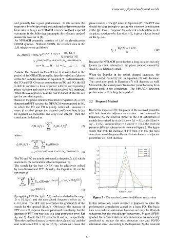
L/Q−1 ∆ f − k)/N). Assume Ω(m) = 6 and N = 1024, the received
2
Õ
J(D, ∆ f ) = J g (D, ∆ f ) , (7) power in different subcarriers is shown in Figure 2. The figure
shows that with the increase of FO from 0 to 0.5, the miss
g=0
where detection rate of the preamble and its interference to adjacent
preambles will both increase.
(g+1)Q−1 L−1
Õ Õ
J g (D, ∆ f ) = Y m,l (Ω(m))
m=gQ l=0
e
× e −j2π∆f (m(N C P +LN)+lN)/N j2πDΩ(m)/N . (8)
The TO and FO are jointly estimated as the pair (D, ∆ f ) which
maximizes the correlation value in Equation (7).
The search for the best (D, ∆ f ) can be effectively solved
by two dimensional FFT. Actually, the Equation (8) can be
rewritten as
(g+1)Q−1 L−1 ! !
Õ Õ −j2π∆f l −j2π∆f m N C P +L N
Y m,l (Ω(m))e e N
m=gQ l=0
j2πΩ(m) D
× e N . (9)
By applying FFT, the J g (D, ∆ f ) can be evaluated in the range Figure 2 – The received power in different subcarriers
D ∈ [0, N CP ) and the normalized frequency offset ∆ f ∈
(−0.5, 0.5). The FFT size determines the granularity of the In this subsection, a new receiver is proposed to solve the
search for the optimal (D, ∆ f ). Obviously, the increase of performance degradation caused by a large FO. The basic
FFT size will improve the computational complexity, but the idea is to make an estimation based on not only the Ω(m)-th
decrease of FFT size may lead to a large estimation error. Let subcarrier, but also the adjacent subcarriers. In each OFDM
S D and S f denote the FFT sizes for D and ∆ f , respectively. symbol, the received data in three subcarriers are coherently
Then the smallest distance between the evaluated ∆ f and the combined to reduce the miss detection rate and FO/TO
real normalized FO is up to 0.5/S f , which will cause the estimation error. According to the Equation (5), the received
– 19 –