
Page 83 - Kaleidoscope Academic Conference Proceedings 2021
P. 83
Connecting physical and virtual worlds
b 1 . As shown in Figure 3, the b −1 and b 1 always have S f to ensure the coherent combination. Therefore, without a
the opposite signs. Therefore the interfering signals in statement, the S f is set to 1024 and 2048 when N rep is
N PRACH
the detected subcarrier and in the adjacent subcarrier will 12 and 24, respectively. Meanwhile, the S D is set to be 1024
counteract each other. Consequently, the correlation peak of for all the cases.
the interfering signals will be suppressed. To detect the transmitted preamble, the BS needs to compute
Example 1 demonstrates the counteraction of the interference the correlation J(D, ∆ f ). The correlation peak is compared
ˆ
from another preamble. with a threshold to determine whether the preamble exists.
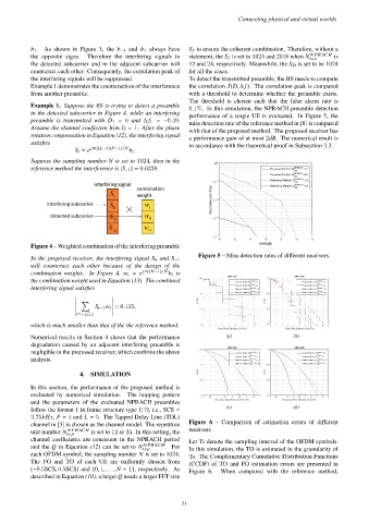
The threshold is chosen such that the false alarm rate is
Example 1. Suppose the BS is trying to detect a preamble 0.1%. In this simulation, the NPRACH preamble detection
in the detected subcarrier in Figure 4, while an interfering performance of a single UE is evaluated. In Figure 5, the
preamble is transmitted with D 1 = 0 and ∆ f 1 = −0.49. miss detection rate of the reference method in [8] is compared
Assume the channel coefficient h(m, l) = 1. After the phase with that of the proposed method. The proposed receiver has
rotation compensation in Equation (12), the interfering signal a performance gain of at most 2dB. The numerical result is
satisfies in accordance with the theoretical proof in Subsection 3.3.
S i = e jπ(∆f 1 −i)(N−1)/N b i .
Suppose the sampling number N is set to 1024, then in the
reference method the interference is |S −1 | = 0.6238.
Figure 4 – Weighted combination of the interfering preamble
Figure 5 – Miss detection rates of different receivers
In the proposed receiver, the interfering signal S 0 and S −1
will counteract each other because of the design of the
combination weights. In Figure 4, w i = e jπi(N−1)/N b i is
the combination weight used in Equation (13). The combined
interfering signal satisfies
Õ
S i−1 w i = 0.135,
i=−1,0,1
which is much smaller than that of the the reference method.
Numerical results in Section 4 shows that the performance (a) (b)
degradation caused by an adjacent interfering preamble is
negligible in the proposed receiver, which confirms the above
analysis.
4. SIMULATION
In this section, the performance of the proposed method is
evaluated by numerical simulation. The hopping pattern
and the parameters of the evaluated NPRACH preambles
follow the format 1 in frame structure type 1[7], i.e., SCS = (c) (d)
3.75kHz, P = 4 and L = 5. The Tapped Delay Line (TDL)
channel in [3] is chosen as the channel model. The repetition Figure 6 – Comparison of estimation errors of different
N PRACH
unit number N rep is set to 12 or 24. In this setting, the receivers
channel coefficients are consistent in the NPRACH period Let Ts denote the sampling interval of the OFDM symbols.
N PRACH
and the Q in Equation (12) can be set to N rep . For In this simulation, the TO is estimated in the granularity of
each OFDM symbol, the sampling number N is set to 1024. Ts. The Complementary Cumulative Distribution Functions
The FO and TO of each UE are uniformly chosen from (CCDF) of TO and FO estimation errors are presented in
(−0.5SCS, 0.5SCS) and {0, 1, . . ., N − 1}, respectively. As Figure 6. When compared with the reference method,
described in Equation (10), a larger Q needs a larger FFT size
– 21 –