
Page 61 - ITU Journal Future and evolving technologies Volume 2 (2021), Issue 6 – Wireless communication systems in beyond 5G era
P. 61
ITU Journal on Future and Evolving Technologies, Volume 2 (2021), Issue 6
model shown in Fig. 8. In Case I, RSs are arranged
linearly at equal intervals (30 m), and totally 64 RSs
are deployed. In Case II, RSs are deployed at four
corners on tops of buildings, and totally 64 RSs are
deployed in 16 buildings in a gridded layout. 12 of
the 16 buildings are 20m height, which are marked
as blue buildings in Fig. 8, and the rest are 30 m
height. The UE, which is assumed to be a vehicle,
moves between buildings. The heights of the BS and
UE are 35 m and 3 m, respectively.
4.1.2 Antenna characteristics
(a) BS antenna
Two-dimensionally arranged planar patch antenna
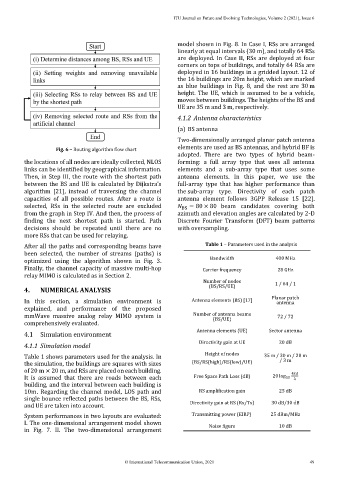
Fig. 6 – Routing algorithm flow chart elements are used as BS antennas, and hybrid BF is
adopted. There are two types of hybrid beam-
the locations of all nodes are ideally collected, NLOS forming: a full array type that uses all antenna
links can be identified by geographical information. elements and a sub-array type that uses some
Then, in Step III, the route with the shortest path antenna elements. In this paper, we use the
between the BS and UE is calculated by Dijkstra’s full-array type that has higher performance than
algorithm [21], instead of traversing the channel the sub-array type. Directivity of each patch
capacities of all possible routes. After a route is antenna element follows 3GPP Release 15 [22].
selected, RSs in the selected route are excluded BS = 80 × 80 beam candidates covering both
from the graph in Step IV. And then, the process of azimuth and elevation angles are calculated by 2-D
finding the next shortest path is started. Path Discrete Fourier Transform (DFT) beam patterns
decisions should be repeated until there are no with oversampling.
more RSs that can be used for relaying.
After all the paths and corresponding beams have Table 1 – Parameters used in the analysis
been selected, the number of streams (paths) is
optimized using the algorithm shown in Fig. 3. Bandwidth 400 MHz
Finally, the channel capacity of massive multi-hop Carrier frequency 28 GHz
relay MIMO is calculated as in Section 2.
Number of nodes 1 / 64 / 1
4. NUMERICAL ANALYSIS (BS/RS/UE)
In this section, a simulation environment is Antenna elements (BS) [17] Planar patch
antenna
explained, and performance of the proposed
mmWave massive analog relay MIMO system is Number of antenna beams 72 / 72
(BS/UE)
comprehensively evaluated.
Antenna elements (UE) Sector antenna
4.1 Simulation environment
4.1.1 Simulation model Directivity gain at UE 20 dB
Table 1 shows parameters used for the analysis. In Height of nodes 35 m / 30 m / 20 m
/ 3 m
the simulation, the buildings are squares with sizes (BS/RS(high)/RS(low)/UE)
of 20 m × 20 m, and RSs are placed on each building. 4
It is assumed that there are roads between each Free Space Path Loss (dB) 20 log 10
building, and the interval between each building is
10m. Regarding the channel model, LOS path and RS amplification gain 25 dB
single bounce reflected paths between the BS, RSs,
and UE are taken into account. Directivity gain at RS (Rx/Tx) 30 dB/30 dB
System performances in two layouts are evaluated: Transmitting power (EIRP) 25 dBm/MHz
I. The one-dimensional arrangement model shown Noise figure 10 dB
in Fig. 7. II. The two-dimensional arrangement
© International Telecommunication Union, 2021 49