
Page 58 - ITU Journal Future and evolving technologies Volume 2 (2021), Issue 6 – Wireless communication systems in beyond 5G era
P. 58
ITU Journal on Future and Evolving Technologies, Volume 2 (2021), Issue 6
where is the noise signal generated in the RS. 3. EXPANSION TO MULTI-HOP
The UE × 1 overall noise vector ( ) is defined as The proposal of massive analog relay MIMO and the
follows. derivation of the optimized channel capacity in
( ) = UE (t) + ( ) (8) single-hop relay is presented in Section 2. However,
RS
practical environments and available locations for
where UE (t) is the UE × 1 noise vector generated RSs could be much more complex than the ideal
at UE. assumptions in Section 2. For example, when
2.5 MIMO channel capacity with beam shapes of streets are irregular and the RSs are
selection unevenly distributed rather than ideally linearly
distributed, there would still exist some areas
From the analysis above, channel capacity of where the mmWave communications are not
SU-Massive MIMO through the artificial MIMO possible even if the signals have been relayed for
channel can be calculated as follows. single hop.
In order to address the problem, in this section, the
s
= B ∑ log (1 + ) (9) proposed system is extended from a single-hop to
w
2
=1 n multi-hop relay system, in which the artificial MIMO
where B w is bandwidth, is -th largest channels are actively generated by multi-hop AF
H
eigenvalue of the channel Gram matrix ( ) ( ), RSs. As shown in Fig. 4, for simplicity of analysis, all
is total transmit power at BS, and is noise RSs are assumed to be deployed at four corners of
s
n
power including the effect of multi-hop relay, which the tops of the buildings because of the good view
is calculated as follows. fields. As the extension of the RSs in a one-
dimensional arrangement in Fig. 1, a two-
2
H
n = E [| ( )| ] (10) dimensional arrangement is shown in Fig. 4, in
which signals from the BS are multi-hop relayed by
where is the eigenvector of the channel Gram RSs to the UE.
matrix corresponding to .
⋆
By taking the beam selection into consideration, 3.1 Extension of artificial channel response
is the maximized , and is calculated as follows. with multi-hop massive analog relay
In order to explain the derivation of an artificial
⋆
= argmax (11)
channel matrix of the multi-hop relay system, all
distributed RSs are virtually arranged in a one-
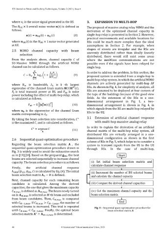
2.6 Sequential quasi-optimization procedure dimensional configuration as shown in the first
column of RSs in Fig. 5, which helps us to consider a
Regarding the beam selection matrix , the system to transmit signals from the BS to the UE
sequential quasi-optimization procedure drawn in through RSs. In the case of multi-hop,
Fig. 3 is widely used to avoid the exhaustive search
as in [19][20]. Based on the prepared , the best
BS
beams are selected sequentially to increase channel
capacity. The beam selection procedure is as follows.
Firstly, the artificial channel response
ℎ URB ( UE , , ) is calculated by Eq. (4). The initial
BS
beam selection matrix = is defined.
0
Next, channel capacity for each remaining beam
candidate is calculated. Among the derived
capacities, the one that gives the maximum capacity
,max is defined as ,max . The beam newly turned
on in ,max is selected as -th beam and excluded
from beam candidates. Then, ,max is compared
with −1,max . If ,max > −1,max , the number of
selected beams is increased. This trial is repeated Fig. 3 – Sequential quasi-optimization procedure for
until ,max < −1,max . Finally, the optimal beam beam selection matrix A
⋆
selection matrix = −1, is determined.
46 © International Telecommunication Union, 2021