
Page 20 - ITU Journal Future and evolving technologies Volume 2 (2021), Issue 6 – Wireless communication systems in beyond 5G era
P. 20
ITU Journal on Future and Evolving Technologies, Volume 2 (2021), Issue 6
the satisfaction of KPI of a set of verticals. In particular, ported in [30], [31], the link between the RRU and the
end users can also belong to more than a slice, and slices cloud server (also considering the delay caused by the
can also be de ined for limited subsets of the network in‐troduction of a virtual environment) would have to
in‐stead of on an end‐to‐end basis. satisfy a latency of 150 µs at a rate of 2457 Mbit s −1 . This
would be the case of softwarizing tasks until the very
The lower lay‐ers. Instead, if we target the softwarization of
Cloud Internet
Big data centres just the up‐per layers, the so‐called Split D, including FEC
and Hybrid Automatic Repeat Request (HARQ), the
requirements re‐lax to 150 µs at a rate of 180 Mbit s −1
Fog
Circuit core domain, User Core (latencies around 1 ms can be accepted at the price of an
Micro/nano
management, Packet core domain, IMS data centres
domain increased error rate, experienced by UEs).
Edge These considerations about C‐RAN can be similar for
Latency Fog Edge Operator’s network other services requiring very low latency. That is why, the
Aggregation points and gateways Micro/nano concepts of fog and edge computing in 5G have emerged.
(wired/wirelss) data centres The de inition of edge is more articulated and less clear
Base stations than the other ones. Speci ically, the idea of edge and Mo‐
and access Fog RAN bile Edge Computing (MEC) derived from the original con‐
points
cept of fog computing, which arose as a more distributed
solution to target URLLC extending the centralised vision
End users
(humans and Fog IoT (with increased latency) provided by cloud computing.
things)
Between 2011 and 2012, the term fog computing was
created within Cisco Systems Inc. and it was de ined as
“[...] a highly virtualized platform that provides compute,
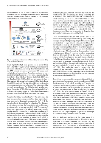
Fig. 5 – Logical high‐level structure of 5G, specifying the location of fog,
cloud, and edge computing. storage, and networking services between end devices
and traditional Cloud Computing Data Centers, typically,
Fig. 5 depicts the high‐level general end‐to‐end architec‐ but not exclusively located at the edge of network.
ture de ined for 5G, graphically clarifying some character‐ [...]” [32]. This de inition actually means that the
istics and initions. As brie ly described in Section 2.1, concept of fog computing, more general than that of
the RAN consists of access points (non‐3GPP access tech‐ MEC [33], [34], means that computing can be distributed
nologies) and base stations. Next, base stations, or more anywhere in be‐tween the cloud and the end users/things,
precisely eNodeBs, consist of two main elements: the Re‐ as correctly un‐derlined by [35].
mote Radio Head (RRH), or Remote Radio Unit (RRU), and
the Baseband Unit (BBU), which are interconnected via a Given these premises and the characteristics of 5G, it is
ibre optical link using the Common Public Radio Inter‐ important to de ine a system providing multi‐access MEC,
face (CPRI) protocol. The aim of the BBU is to perform the that is a network “[...] which provides an IT service en‐
processing due to the lower layers of the wireless cellular vironment and cloud‐computing capabilities at the edge
network protocol stack. The BBU also deals with Forward of an access network which contains one or more type
Error Correction (FEC), Medium Access Control (MAC), of access technology, and in close proximity to its users.
and encryption/decryption of Packet Data Convergence [...]” [36]. So, what can we name as ’edge’? First, it
Protocol (PDCP) uplink/downlink communications. is possible to say that the edge of the network depends
on the speci ic vertical that is targeted. Next, if we con‐
Next, the front haul is de ined as “[...] The intra‐base sta‐ sider the virtualisation of BBU functionalities within edge
tion transport, in which a part of the base station func‐ micro/nano data centres, the initially‐clear de inition of
tion is moved to the remote antenna site. [...]” [14]. On RAN overlaps with the edge, and it can still be accurate to
the other hand, the back haul is de ined as “[...] The net‐ say that the RAN becomes a subset of the edge. Thus, the
work path connecting the base station site and the net‐ clear separation, graphically shown in Fig. 5, would be‐
work controller or gateway site. [...]” [14]. These two def‐ come more shaded. Recently, there has been a harmoni‐
initions are important to be taken into account once dis‐ sation process between different standardization efforts
cussing how 5G includes the virtualisation paradigm of C‐ by ETSI and 3GPP regarding MEC [37], towards the design
RAN. By employing and implementing C‐RAN, the BBU is of a common unique architecture for 5G MEC.
softwarized and so, it runs in a virtual environment (for
example, in a virtual machine or a container), which is After the high‐level architectural discussion above, it is
normally placed in the cloud. This means that the tasks important to show some details about 5G architecture as
of each layer of the BBU, mentioned in the previous para‐ expressed in the latest published 3GPP release [38]. By
graphs, have to seamlessly be performed in a cloud data now, 5G New Radio (NR) has been the principal standard‐
centre. However, by looking at Fig. 5, this implies a sig‐ ization effort. This has the scope of providing an ef icient
ni icant increase in latency. If we assume the values re‐ and effective access network in order to connect different
8 © International Telecommunication Union, 2021