
Page 100 - ITU Journal Future and evolving technologies Volume 2 (2021), Issue 4 – AI and machine learning solutions in 5G and future networks
P. 100
ITU Journal on Future and Evolving Technologies, Volume 2 (2021), Issue 4
3. NETWORK TOPOLOGY ANALYSIS FOR
OPTIMIZATION
Topology optimization is quite complicated.
Existing network topology planning can hardly
satisfy future traffic increase or solve the problem
of uneven load balancing, as it is made based on the
current network load. Our research is to resolve this
problem through dynamic network topology
optimization. Specifically, the topology
optimization system introduced in this paper
enables network load balancing and makes the
topology satisfy future traffic growth.
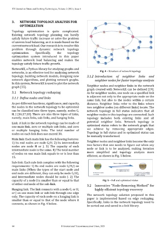
NetworkX, a Python library for studying graphs and
networks, is an effective tool for analyzing network Fig. 4 – Structure of network topology
topology, building network models, designing new 3.1.2 Introduction of neighbor links and
network algorithms, and plotting network graphs. neighbor nodes for faster topology analysis
In this system, NetworkX is used to plot the network
graph [15]. Neighbor nodes and neighbor links in the network
graph created with NetworkX can be defined [19].
3.1 Network topology reshaping As for neighbor nodes, one node on a specified link
3.1.1 Define nodes and links is adjacent not only to the appropriate node on the
same link, but also to the nodes within a certain
As per different functions, significance, and capacity, distance. Neighbor links refer to the links where
the nodes in the network topology to be optimized two neighbor nodes (on different links) locate. The
can be classified into three types, namely, nodes G, network topology in full status indicates that all
H, J [16,17,18]. There are also three types of links, neighbor nodes in this topology are connected. Such
namely, main links, sub-links, and hanging links. topology includes both existing links and all
Link: A link in the network topology can be made of potential neighbor links. Network topology in
one main link, zero or multiple sub-links, and zero optimized status refers to the network graph that
or multiple hanging links. The total number of we achieve by removing appropriate edges.
nodes on each link does not exceed 30. Topology in full status and in optimized status can
be mutually transformed.
Main link: Each main link has the following features:
1) Its end nodes are node G/H. 2) Its intermediate Neighbor nodes and neighbor links become the only
nodes are node H or J. 3) The capacity of each two factors that one needs to figure out when any
intermediate node is the same. 4) The total number node or link is to be analyzed, making iteration
of nodes on one main link equals to or is less than more simplified and topology analysis more
15. efficient, as shown in Fig. 5 below.
Sub-link: Each sub-link complies with the following
requirements: 1) Its end nodes are node G/H/J on
main links (When the types of the start node and
end node are different, they can only be node G/H),
and intermediate nodes should be node J. 2) The
capacity of a node J is smaller than or equal to that Fig. 5 – Full and optimized status
of either end node of the sub-link. 3.2 Innovative "Node-Removing Method" for
Hanging link: The link connects with a node G, or H, highly efficient topology recovery
or J on one main link or sub-link through one edge
only. The capacity of each node on a hanging link is The network topology solution proposed in this
smaller than or equal to that of the node where it paper is implemented based on edge reshaping.
connects, as shown in Fig. 4 below. Specifically, links in the network topology need to
be sorted out and saved in a link library.
84 © International Telecommunication Union, 2021