
Page 175 - ITU Journal Future and evolving technologies – Volume 2 (2021), Issue 2
P. 175
ITU Journal on Future and Evolving Technologies, Volume 2 (2021), Issue 2
in practical communication systems (DMC or other digi‑ = − 1 elements are removed from each row of the
tal communication systems), it is the SNR that determines detection matrix , . According to the results shown in
the achievable performance. No matter how high is the Fig. 3, we have the following observations. First, the BER
transmit power (i.e., the number of molecules emitted per performance of the MTH‑MoSK DMC systems employing
pulse in DMC), the communication systems’ performance either detection schemes degrades with the increase of
will be poor, if the SNR generated by the receiver is low. the number of nano‑machines, as the result of MAI. When
To set the parameters in our simulations, when given an ≥ 2, the EGC‑IM scheme outperforms the conventional
SNR and a volume of detection space, ( ) is calculated EGC scheme, provided that SNR is suf iciently high. This
by (9). Then, when given a transmission distance be‑ observation becomes clearer when is larger and SNR is
tween nano‑machines and AP, the number of molecules higher. However, if SNR is low, the EGC‑IM may be outper‑
emitted to transmit one bit can be obtained with the formed by the conventional EGC scheme. The reason be‑
aid of (2). Since an MTH‑MoSK DMC system employs the hind this is that when SNR is low, system performance is
‑ary MoSK to transmit log bits per symbol, a nano‑ dominated by background noise. In this case, combining
2
machine can emit in total = log × molecules more samples encourages smooth noise and hence im‑
2
for transmission of one symbol. However, as one sym‑ proves BER performance. By contrast, when SNR is rel‑
bol is transmitted by pulses in chips, the number of atively high, system performance is dominated by MAI.
molecules emitted per chip is = / . Hence, the proposed EGC‑IM scheme with the capability
ℎ
ℎ
Additionally, there are some parameters ixed in our sim‑ of MAI mitigation outperforms the conventional EGC de‑
ulations, these include the similar distance of = 250 tection.
2
from each nano‑transmitter to AP, = 2.2 × 10 −9 /
-5
2
-9
3
and = 4 with = 20 nm. Moreover, we set the Parameters:D=2.2 10 m /s, =20nm,T =6 10 s,M=16,K=4,J=1
3 b
bit duration as = 6 × 10 −5 , giving the symbol du‑
−5
ration of = log × (6 × 10 ) ( ). Hence, when
2
there are chips per symbol, the chip duration is given 10 -1
−5
by = / = log × (6 × 10 )/ ( ). Finally, the
ℎ
2
length of ISI is set as the value of
-2
10
BER
≜ arg { ℎ( ) ≤ 0.1%} (10)
-3
10
ℎ( )
EGC-IM (L=4)
EGC-IM (L=6)
which means that the interference 30 below the signal EGC-IM (L=8)
10 -4 EGC (L=4)
power is ignored. EGC (L=6)
EGC (L=8)
-5
2
-9
Parameters:D=2.2 10 m /s, =20nm,T =6 10 s,M=16,L=8,J=K-1
0 b 10 -5
10 EGC (K=1) 0 2 4 6 8 10 12 14 16 18 20
EGC-IM (K=2) SNR(dB)
EGC-IM (K=4)
EGC-IM (K=6)
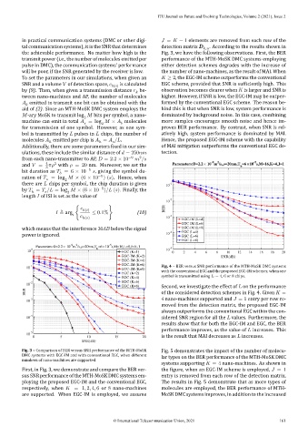
-1 Fig. 4 – BER versus SNR performance of the MTH‑MoSK DMC systems
10 EGC-IM (K=8)
with the conventional EGC and the proposed EGC‑IM schemes, when one
EGC (K=2)
EGC (K=4) symbol is transmitted using = 4, 6 or 8 chips.
-2 EGC (K=6)
10
EGC (K=8) Second, we investigate the effect of on the performance
BER of the considered detection schemes in Fig. 4. Given =
-3 4 nano‑machines supported and = 1 entry per row re‑
10
moved from the detection matrix, the proposed EGC‑IM
always outperforms the conventional EGC within the con‑
-4
10 sidered SNR region for all the values. Furthermore, the
results show that for both the EGC‑IM and EGC, the BER
performance improves, as the value of increases. This
-5
10
0 5 10 15 20 is the result that MAI decreases as increases.
SNR(dB)
Fig. 3 – Comparison of BER versus SNR performance of the MTH‑MoSK Fig. 5 demonstrates the impact of the number of molecu‑
DMC systems with EGC‑IM and with conventional EGC, when different
lar types on the BER performance of the MTH‑MoSK DMC
numbers of nano‑machines are supported.
systems supporting = 4 nano‑machines. As shown in
First, in Fig. 3, we demonstrate and compare the BER ver‑ the igure, when an EGC‑IM scheme is employed, = 1
sus SNR performance of the MTH‑MoSK DMC systems em‑ entry is removed from each row of the detection matrix.
ploying the proposed EGC‑IM and the conventional EGC, The results in Fig. 5 demonstrate that as more types of
respectively, when = 1, 2, 4, 6 or 8 nano‑machines molecules are employed, the BER performance of MTH‑
are supported. When EGC‑IM is employed, we assume MoSK DMC systems improves, in addition to the increased
© International Telecommunication Union, 2021 161