
Page 134 - ITU Journal, ICT Discoveries, Volume 3, No. 1, June 2020 Special issue: The future of video and immersive media
P. 134
ITU Journal: ICT Discoveries, Vol. 3(1), June 2020
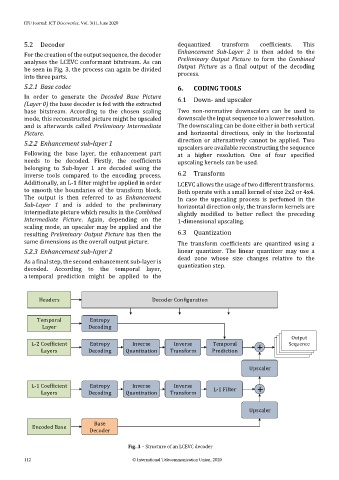
5.2 Decoder dequantized transform coefficients. This
For the creation of the output sequence, the decoder Enhancement Sub-Layer 2 is then added to the
analyses the LCEVC conformant bitstream. As can Preliminary Output Picture to form the Combined
be seen in Fig. 3, the process can again be divided Output Picture as a final output of the decoding
into three parts. process.
5.2.1 Base codec 6. CODING TOOLS
In order to generate the Decoded Base Picture 6.1 Down- and upscaler
(Layer 0) the base decoder is fed with the extracted
base bitstream. According to the chosen scaling Two non-normative downscalers can be used to
mode, this reconstructed picture might be upscaled downscale the input sequence to a lower resolution.
and is afterwards called Preliminary Intermediate The downscaling can be done either in both vertical
Picture. and horizontal directions, only in the horizontal
5.2.2 Enhancement sub-layer 1 direction or alternatively cannot be applied. Two
upscalers are available reconstructing the sequence
Following the base layer, the enhancement part at a higher resolution. One of four specified
needs to be decoded. Firstly, the coefficients upscaling kernels can be used.
belonging to Sub-layer 1 are decoded using the
inverse tools compared to the encoding process. 6.2 Transform
Additionally, an L-1 filter might be applied in order LCEVC allows the usage of two different transforms.
to smooth the boundaries of the transform block. Both operate with a small kernel of size 2x2 or 4x4.
The output is then referred to as Enhancement In case the upscaling process is perfomed in the
Sub-Layer 1 and is added to the preliminary horizontal direction only, the transform kernels are
intermediate picture which results in the Combined slightly modified to better reflect the preceding
Intermediate Picture. Again, depending on the 1-dimensional upscaling.
scaling mode, an upscaler may be applied and the
resulting Preliminary Output Picture has then the 6.3 Quantization
same dimensions as the overall output picture. The transform coefficients are quantized using a
5.2.3 Enhancement sub-layer 2 linear quantizer. The linear quantizer may use a
dead zone whose size changes relative to the
As a final step, the second enhancement sub-layer is
decoded. According to the temporal layer, quantization step.
a temporal prediction might be applied to the
Headers Decoder Configuration
Temporal Entropy
Layer Decoding
Output
L-2 Coefficient Entropy Inverse Inverse Temporal + Sequence
Layers Decoding Quantization Transform Prediction
Upscaler
L-1 Coefficient Entropy Inverse Inverse L-1 Filter +
Layers Decoding Quantization Transform
Upscaler
Base
Encoded Base
Decoder
Fig. 3 – Structure of an LCEVC decoder
112 © International Telecommunication Union, 2020