
Page 89 - ITU Journal, Future and evolving technologies - Volume 1 (2020), Issue 1, Inaugural issue
P. 89
ITU Journal on Future and Evolving Technologies, Volume 1 (2020), Issue 1
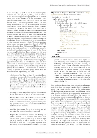
In the final step, we seek to match the scattering field Algorithm 1 Physical Element Calibration. High-
response (i.e. the (A 1 e iφ 1 , A 2 e iφ 2 ) i,j pairs calculated lighted commands run in a separate thread.
in the previous step) to the appropriate set of element Set index to i = 0, j = 0
states, such as the resistance R and reactance X (ca- while index does not exceed max do
pacitance or inductance) of the loads, for all unit cells Get S ij ; Get Tol
indexed by i, j. The correspondence between the scat- if !(exists S db where |S db − S ij | < Tol) then
tering response of a unit cell and its physical structure while searching do
constitutes a highly complex and demanding propaga- Select node where state == free
tion problem. Actually, the search for a proper set of Set to busy
states for a fully defined response constitutes an inverse Initiate parallel thread;
problem with closed-form solutions available only for Optimizer: Fixes (R, L, C, D) variables;
very simple unit cell types. As such, it demands the use Optimizer → Requests new simulation;
of highly efficient optimization algorithms and strong
node ← Returns S sim
computation power to perform the necessary numerical S db = S sim ;
simulations. In our implementation, we employ a cluster if |S sim − S ij | < Tol then
of interconnected computer clients (that serve as simu- searching = false
lation nodes) receiving instructions through a TCP/IP Set (R, L, C, D) variables as optimal
network from the host Metamaterial Middleware run- end if
ning on the main machine. In a lightweight scenario, Set node state to free
a single-cell simulation assigned to one of the clients end while
can be completed in less than a minute but this may Iterate index
grow substantially when the complexity of the design is end if
increased. An acceptable convergence is expected to be end while
reached within a few thousands simulation trials. In per-
spective, the prototype studied in this work displayed a process and a new series of simulations begins un-
typical evaluation time of 8 to 12 hours for a full char- til a sufficiently close convergence to the targeted
acterization of its configuration space and all possible scattering field response S ij =(A 1 e iφ 1 , A 2 e iφ 2 ) i,j is
impinging plane waves (θ,φ sets) at the operation fre- achieved. Prior to each simulation, the optimizer
quency of the hardware. The evaluation is performed looks up all entries in the associated table of the
through Algorithm 1 (see next page) whose steps are configuration DB, in case a result (S db ) is already
described below. Specifically, the user: stored. If not, the simulation will start and the
result will be stored afterwards. Over time, this
selects one of the three options: i) a gradient based process can populate the DB with enough results,
optimizer, recommended for a small number of vari- making option (iii) of the initial step a highly effi-
ables (less than four), ii) a metaheuristic optimizer, cient method for evaluating new functionalities for
recommended for a higher count of variables (more this particular tile.
than three), and iii) a database-based optimization
process that configures the proper switch-states, By completing the previous steps, the software has suc-
through simulation results already stored in the cessfully defined a new configuration for the chosen tile,
configuration DB. which, now, remains to be stored in the configuration
DB. Before doing so, we can apply an additional evalu-
suggests a convergence limit Tol to the optimizer
ation step by conducting an experimental measurement
in the Tolerance text box for all variable targets,
on a physical prototype (if available). Our current im-
plementation is able to assess multi-splitting or absorp-
fills the IP list with all available simulation nodes
tion functionalities by measuring the full scattering dia-
and initiates a connection. All nodes will launch the
gram on the front metamaterial hemisphere, which can
installed simulation software, open the correspond-
then be compared to the scattering profile produced
ing geometry model, and remain idle until further
by the software. As presented in the corresponding
instructions are received.
technical report [20], several tests with a metamaterial
modifies, if necessary, the value range, step and ini- unit have already been successfully conducted in a fully
tial value for each variable in the unit cell. equipped anechoic chamber (Fig. 11). This test bed
incorporates a variety of algorithms, meeting individual
begins the optimization process by clicking the needs for accuracy and speed for various cases of scat-
“RUN” button. The software will iterate over tering response measurements (e.g. a full 3D-pattern
all unit cells (from top-left (0, 0) to bottom-right versus a 2D-slice might be required for arbitrary lobe
(N, M)), seeking a set of optimal values for the scattering). A simple case is outlined in Algorithm 2,
variables of each cell. During this sequence, each where the user has previously set the appropriate pa-
unit cell (i, j) initiates an independent optimization rameters in the GUI (Fig. 11(c)). The GUI automates
© International Telecommunication Union, 2020 69