
Page 91 - ITU Journal, Future and evolving technologies - Volume 1 (2020), Issue 1, Inaugural issue
P. 91
ITU Journal on Future and Evolving Technologies, Volume 1 (2020), Issue 1
Algorithm 2 Evaluate Scattering Response, 3D, slow
rotation case. Highlighted commands refer to HW in-
structions.
Set N ← number of equidistant points on the hemi-
sphere
Set P[N] ← Struct of (θ, φ) points
for all elements i in P do
Send rotation command → Positioner
(Mast - P[i].theta, Head - P[i].phi, Speed)
Receive ← Positioner feedback
Refresh 3D Figure
Send measurement command → VNA
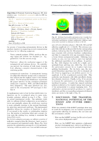
E[i] = Receive ← S21 power Fig. 13 – Arbitrary functionality optimization test. A smiley face-
Refresh Plot graph shaped scattering pattern is successfully produced (left). The cor-
responding metamaterial element configuration (different meta-
end for
atom states expressed in colormap) is shown to the left.
Save (P[i],E[i]) to DB
unit cell with reflection phases (−90, 0, 90, 180) and full
the process of measuring metamaterial devices in the reflection amplitude (A = 1) [14,38]. The outcome com-
anechoic chamber by supporting several communication plies fully with the results provided by the corresponding
interfaces for the following equipment: authors, indicating that the Metamaterial Middleware
may cooperate with arbitrary hardware configurations
Vector network analyzer (VNA): produces the en- and thus be compatible with any reasonable design in
ergy signal and receives the response (i.e. S 21 - a future diverse metamaterial market. Following these
parameter) from the antenna setup. results, we, also, test four exclusive cases that highlight
the additional capabilities of our software. In particu-
Positioner: allows the mechanical support of the
lar, Fig. 12(b) displays the results for a triple- and a
metamaterial and antenna devices. Its controller
quintuple-beam splitting case, while Fig. 12(c) shows
can instruct the rotation of both heads (towards
the optimization outcome for an in-plane triple-beam
θ, φ), allowing a complete characterization of the
splitting functionality. For the latter case, the inte-
scattering profile.
grated theoretical algorithms were able to eliminate all
side lobes by suggesting a non-uniform pattern for the
metamaterial controllers: A metamaterial hosting
amplitude A of the co-polarized scattered field. This
reconfigurable elements incorporates a communica-
particular case demands a tile with controllable absorp-
tion network for the explicit control of its element
tion elements (resistors). Finally, in Fig. 13 we proceed
states. The Metamaterial Middleware implements
to showcase the optimization of an arbitrary departing
the proper interface for the evaluation prototypes
wavefront formation. A smiley-face shaped scattering
(serial port connection, WiFi, and Bluetooth have
pattern is selected as the required energy wave response
been integrated). The same interfaces are, also,
of the metamaterial to a planar impinging wave. The
used for the metamaterial API developed in Sec-
optimization process successfully produces the required
tion 4.
wavefront, and the corresponding metamaterial element
A supplementary note is that the final switch-state con- states are shown to the right of Fig. 13.
figuration can be re-evaluated using the same meta-
heuristic optimizer utilized in step 3 of Fig. 12(a) 7. DISCUSSION: THE TRANSFOR-
via actual experimental results. The optimizer starts MATIONAL POTENTIAL OF THE
with the software-defined configuration as an initial so- IOMMT AND FUTURE DIREC-
lution and gradually adjusts the switch-state matrices TIONS
to more optimally converge to the pursued functional-
ity under true operational conditions. The implemented While the potential of the IoMMT paradigm alone may
algorithm follows the template of Algorithm 2, where be worth the investigation, here we evaluate its practical
N correspond to the number or optimization variables opportunities affecting the industry, the end users and
(e.g. the number of scattering lobes) and a second for the environment, namely:
loop nests the existing loop, seeking to maximize the
Sum i (E[i]) metric. How can the IoMMT prolong the life cycle of prod-
For further evaluation purposes, we validate a number of ucts across deployment scales?
indicative examples from the literature, based on previ-
ously measured and simulated results. Hence, Fig. 12(a) How can the IoMMT help maintain a high-speed
presents the optimization outcome for a 4-bit metamate- product development pace, without sacrificing eco-
rial array, which can switch over four available states per logical concerns during the product design phase?
© International Telecommunication Union, 2020 71