
Page 102 - ITU Journal, Future and evolving technologies - Volume 1 (2020), Issue 1, Inaugural issue
P. 102
ITU Journal on Future and Evolving Technologies, Volume 1 (2020), Issue 1
assigned to the meta-surface. In this context, the momen-
tum conservation law for wave vectors can be expressed
as
Φ
( ) (Φ ) + = ( ) (Φ ) (5)
Φ
( ) (Φ ) + = ( ) (Φ ) (6) (a)
where Φ / and Φ / describe the gradients along
the ̂x- and ̂y- directions, respectively. For simplicity we
consider the normal incident wave case i.e., ( = Φ = 0)
in lossless medium scenario [14]. Assuming air as the
medium of the incident and reflected wave, we can sim-
plify the formulations above as
2 Φ 2 Φ
Φ = , Φ = ,
0 0
(7) (b)
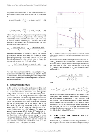
which demonstrate the phase shift Φ and Φ that need to Fig. 3 – Simulated results for the proposed unit cell in two ON and OFF
be performed per unit of distance (i.e., and ) along situations, expressed in terms of (a) reflection magnitude and (b) reflec-
the ̂x and ̂y directions, respectively. Then, in Eq. (6) we set tion phases.
the unit cell size as = = , in order to obtain the In order to assess the double negative characteristics, 11
phase required at the ( , )-th unit cell as and 21 reflection and transmission coefficients are ex-
2 ( Φ + Φ ) tracted from the design in CST in both magnitude and an-
Φ = 0 . (8) gle (expressed in rad). Then, the effective permittivity
and effective permeability
tively as [20]: are obtained respec-
For beam-steering functionality the required phase Φ
is calculated for all the unit cells, to assign radiated states 1 −1 [ 1 (1 − 2 + )]
2
to each unit cell. Then, a closest neighbor mapping is done = 2 21 11 21 , (9)
2
between the required phase and that provided by the dif- √ (1+ 11 ) − 2 21
2
ferent unit cell states. (1− 11 ) − 2 21
and
3. SIMULATION RESULTS
2
In this section, we evaluate the performance of the unit 1 1 (1 + ) − 2
2
= −1 [ (1 − 2 + )] √ 11 21 ,
cell we designed. The simulation is realized by the means 2 21 11 21 (1 − ) − 2 21
2
11
of a commercial software CST studio suite. The specific (10)
configuration considered in CST is the boundary condi-
where denotes the wave number of the incident wave
tion as unit cell in ̂x- and ̂y-directions with open-add
and [mm] is the thickness of the unit cell. In this study,
space in ̂z-direction. The reflectivity and reflection phases
the meta-surface is printed on an FR-4 substrate with
of unit cells are simulated using the frequency domain
thickness of 1.6 mm and is designed to increase the direc-
solver. The simulated reflection magnitude and phase of
the unit cell are shown in Fig. 3. It is obvious that at 5.3 tivity and bandwidth of the structure. Fig. 4 shows the ef-
fective permittivity and effective permeability related to
GHz, while the reflection magnitude is almost identical
the designed unit cell. It is clear that the proposed unit
between the ON and OFF state, the reflection phase be- cell has double-negative material characteristics around
∘
tween the two cases has a 180 change. The maximum
5.3 GHz for both ON and OFF states.
unit cell loss is around 2.5 dB for the OFF state. It is ev-
ident that the proposed 1-bit unit cell is suitable for the
multifunctional meta-surface such as coding and beam 4. FULL STRUCTURE DESCRIPTION AND
steering. As the phase change between ON/OFF states is EVALUATION
relative, we can simply state that a unit cell with an ON
∘
state corresponds to a 0 phase reflection, while one with In this section, in order to evaluate the performance of
∘
an OFF state has a −180 phase reflection. the proposed unit cell for multifunctional applications, a
82 © International Telecommunication Union, 2020