
Page 20 - ITU Journal: Volume 2, No. 1 - Special issue - Propagation modelling for advanced future radio systems - Challenges for a congested radio spectrum
P. 20
ITU Journal: ICT Discoveries, Vol. 2(1), December 2019
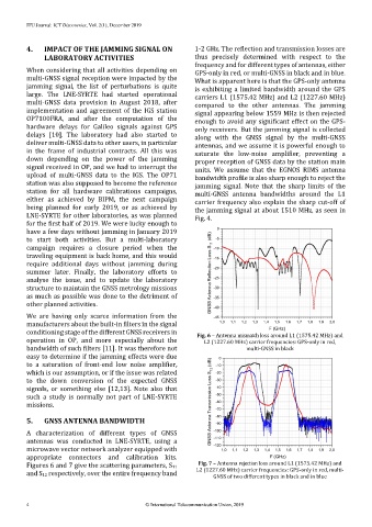
4. IMPACT OF THE JAMMING SIGNAL ON 1-2 GHz. The reflection and transmission losses are
LABORATORY ACTIVITIES thus precisely determined with respect to the
frequency and for different types of antennas, either
When considering that all activities depending on GPS-only in red, or multi-GNSS in black and in blue.
multi-GNSS signal reception were impacted by the What is apparent here is that the GPS-only antenna
jamming signal, the list of perturbations is quite is exhibiting a limited bandwidth around the GPS
large. The LNE-SYRTE had started operational carriers L1 (1575.42 MHz) and L2 (1227.60 MHz)
multi-GNSS data provision in August 2018, after compared to the other antennas. The jamming
implementation and agreement of the IGS station signal appearing below 1559 MHz is then rejected
OP7100FRA, and after the computation of the enough to avoid any significant effect on the GPS-
hardware delays for Galileo signals against GPS only receivers. But the jamming signal is collected
delays [10]. The laboratory had also started to along with the GNSS signal by the multi-GNSS
deliver multi-GNSS data to other users, in particular antennas, and we assume it is powerful enough to
in the frame of industrial contracts. All this was saturate the low-noise amplifier, preventing a
down depending on the power of the jamming proper reception of GNSS data by the station main
signal received in OP, and we had to interrupt the units. We assume that the EGNOS RIMS antenna
upload of multi-GNSS data to the IGS. The OP71 bandwidth profile is also sharp enough to reject the
station was also supposed to become the reference jamming signal. Note that the sharp limits of the
station for all hardware calibrations campaigns, multi-GNSS antenna bandwidths around the L1
either as achieved by BIPM, the next campaign carrier frequency also explain the sharp cut-off of
being planned for early 2019, or as achieved by the jamming signal at about 1510 MHz, as seen in
LNE-SYRTE for other laboratories, as was planned Fig. 4.
for the first half of 2019. We were lucky enough to
have a few days without jamming in January 2019
to start both activities. But a multi-laboratory
campaign requires a closure period when the
traveling equipment is back home, and this would
require additional days without jamming during
summer later. Finally, the laboratory efforts to
analyse the issue, and to update the laboratory
structure to maintain the GNSS metrology missions
as much as possible was done to the detriment of
other planned activities.
We are having only scarce information from the
manufacturers about the built-in filters in the signal
conditioning stage of the different GNSS receivers in Fig. 6 – Antenna mismatch loss around L1 (1575.42 MHz) and
operation in OP, and more especially about the L2 (1227.60 MHz) carrier frequencies: GPS-only in red,
bandwidth of such filters [11]. It was therefore not multi-GNSS in black
easy to determine if the jamming effects were due
to a saturation of front-end low noise amplifier,
which is our assumption, or if the issue was related
to the down conversion of the expected GNSS
signals, or something else [12,13]. Note also that
such a study is normally not part of LNE-SYRTE
missions.
5. GNSS ANTENNA BANDWIDTH
A characterization of different types of GNSS
antennas was conducted in LNE-SYRTE, using a
microwave vector network analyzer equipped with
appropriate connectors and calibration kits.
Figures 6 and 7 give the scattering parameters, S11 Fig. 7 – Antenna rejection loss around L1 (1575.42 MHz) and
and S12 respectively, over the entire frequency band L2 (1227.60 MHz) carrier frequencies: GPS-only in red, multi-
GNSS of two different types in black and in blue
4 © International Telecommunication Union, 2019