
Page 18 - ITU Journal: Volume 2, No. 1 - Special issue - Propagation modelling for advanced future radio systems - Challenges for a congested radio spectrum
P. 18
ITU Journal: ICT Discoveries, Vol. 2(1), December 2019
des Fréquences (ANFR) [7]. Section 3 is showing Computations of all OP collected GNSS data is
what was observed and the effects of this jamming carried out daily for monitoring purposes. It
signal on some of OP stations. Section 4 describes provides among other results CV between stations,
the impact of the jamming signal on laboratory based on an ionosphere-free P3 linear combination
activities. Section 5 details the influence of the of GPS data [8] in the CGGTTS file format [9] over
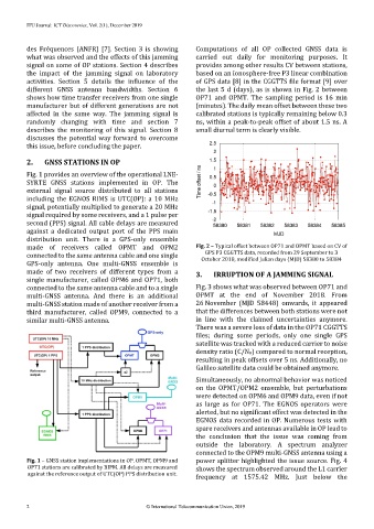
different GNSS antenna bandwidths. Section 6 the last 5 d (days), as is shown in Fig. 2 between
shows how time transfer receivers from one single OP71 and OPMT. The sampling period is 16 min
manufacturer but of different generations are not (minutes). The daily mean offset between these two
affected in the same way. The jamming signal is calibrated stations is typically remaining below 0.3
randomly changing with time and section 7 ns, within a peak-to-peak offset of about 1.5 ns. A
describes the monitoring of this signal. Section 8 small diurnal term is clearly visible.
discusses the potential way forward to overcome
this issue, before concluding the paper.
2. GNSS STATIONS IN OP
Fig. 1 provides an overview of the operational LNE-
SYRTE GNSS stations implemented in OP. The
external signal source distributed to all stations
including the EGNOS RIMS is UTC(OP): a 10 MHz
signal, potentially multiplied to generate a 20 MHz
signal required by some receivers, and a 1 pulse per
second (PPS) signal. All cable delays are measured
against a dedicated output port of the PPS main
distribution unit. There is a GPS-only ensemble
made of receivers called OPMT and OPM2 Fig. 2 – Typical offset between OP71 and OPMT based on CV of
GPS P3 CGGTTS data, recorded from 29 September to 3
connected to the same antenna cable and one single October 2018, modified Julian days (MJD) 58380 to 58384
GPS-only antenna. One multi-GNSS ensemble is
made of two receivers of different types from a 3. IRRUPTION OF A JAMMING SIGNAL
single manufacturer, called OPM6 and OP71, both
connected to the same antenna cable and to a single Fig. 3 shows what was observed between OP71 and
multi-GNSS antenna. And there is an additional OPMT at the end of November 2018. From
multi-GNSS station made of another receiver from a 26 November (MJD 58448) onwards, it appeared
third manufacturer, called OPM9, connected to a that the differences between both stations were not
similar multi-GNSS antenna. in line with the claimed uncertainties anymore.
There was a severe loss of data in the OP71 CGGTTS
files; during some periods, only one single GPS
satellite was tracked with a reduced carrier to noise
density ratio (C/N0) compared to normal reception,
resulting in peak offsets over 5 ns. Additionally, no
Galileo satellite data could be obtained anymore.
Simultaneously, no abnormal behavior was noticed
on the OPMT/OPM2 ensemble, but perturbations
were detected on OPM6 and OPM9 data, even if not
as large as for OP71. The EGNOS operators were
alerted, but no significant effect was detected in the
EGNOS data recorded in OP. Numerous tests with
spare receivers and antennas available in OP lead to
the conclusion that the issue was coming from
outside the laboratory. A spectrum analyzer
connected to the OPM9 multi-GNSS antenna using a
Fig. 1 – GNSS station implementations in OP. OPMT, OPM9 and power splitter highlighted the issue source. Fig. 4
OP71 stations are calibrated by BIPM. All delays are measured shows the spectrum observed around the L1 carrier
against the reference output of UTC(OP) PPS distribution unit.
frequency at 1575.42 MHz. Just below the
2 © International Telecommunication Union, 2019