
Page 772 - 5G Basics - Core Network Aspects
P. 772
2 Transport aspects
The last two 4-dimensional elements in each symbol, and at the end of the RMC part of an RMC symbol,
shall be chosen to force the convolutional encoder state to the zero state. For each of these symbols, the
two LSBs of u are predetermined, and only (x y − 3) bits shall be extracted from the data frame buffer and
shall be allocated to (tz tz-1 …. t4 t3).
NOTE – The above requirements imply a minimum size of the b' table of four non-zero entries. The minimum number
of non-zero entries in the corresponding b table could be higher.
10.2.1.3.1.2 RMC symbols
Bits of the RMC portion of the RMC data frame after padding shall be extracted in sequential order
according to the re-ordered bit allocation table bRMC'. The first bit of the RMC portion of the RMC data
frame shall be extracted first. The extraction is based on pairs of consecutive bRMC' entries. Furthermore,
due to the constellation expansion associated with trellis coding, the bit allocation table bRMC' specifies the
number of coded bits per subcarrier of the RMC portion of the RMC symbol.
Trellis coding shall be performed on pairs of consecutive bRMC' values. If the number of non-zero entries in
the bRMC' table is even, trellis coding shall start with the first non-zero entry in the bRMC' table. If the number
of non-zero entries in the bRMC' table is odd, trellis coding shall start from a zero entry preceding the first
non-zero entry in table bRMC' (to make an integer number of pairs).
Bits of the DTU part of the RMC data frame after padding shall be extracted in sequential order according
to the re-ordered bit allocation table bDR'. The rules of extraction are the same as for the RMC portion.
10.2.1.3.2 Bit conversion
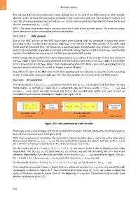
The binary word u (uz', uz'−1, ... , u1) constructed from bits (tz tz-1… t1) extracted LSB first from the data
frame buffer as defined in Table 10-2 is converted into two binary words: v (vz'−y, ... , v0) and
w = (wy−1, ... , w0), which are both inserted LSB first in the encoded data buffer and used to look up
constellation points in the constellation mapper (see Figure 10-5).
Figure 10-5 – Bit conversion by trellis encoder
The binary word v shall be input first to the constellation mapper, LSB first, followed by the binary word w,
also LSB first (reference point B in Figure 10-5).
NOTE – For convenience of description, the constellation mapper identifies these x and y bits with a label whose
binary representation is (vb−1, vb−2, ... , v1, v0). The same constellation mapping rules apply to both the v (with b = x) and
the w (with b = y) vector generated by the trellis encoder (see clause 10.2.1.4.1).
For the usual case of x 1 and y 1, z' z x + y − 1, and binary words v and w contain x and y bits,
respectively. The bits (u3, u2, u1) determine (v1, v0) and (w1, w0) and the remaining bits of v and w are
obtained, respectively, from the LSBs and MSBs of the word (uz', uz'−1, ... , u4), according to Figure 10-6, i.e.,
if x 1 and y 1, v (uz'−y+2, uz'−y+1, ... , u4, v1, v0) and w (uz', uz'−1, ... , uz'−y+3, w1, w0).
For the special case of x 0 and y 1, z' z + 2 y + 1, v (v1, v0) (0, 0) and w (wy−1, ... , w0).
The convolutional encoder shown in Figure 10-6 is a systematic encoder (i.e., u1 and u2 are passed through
unchanged) as shown in Figure 10-7. The convolutional encoder state (S3, S2, S1, S0) is used to label the
states of the trellis shown in Figure 10-9. At the beginning of a symbol, the convolutional encoder state
shall be initialized to (0, 0, 0, 0).
762