
Page 762 - 5G Basics - Core Network Aspects
P. 762
2 Transport aspects
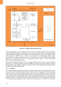
Figure 10-1 – PMD functional reference model
In the receive direction, the incoming signal from the line (U-O interface) during the time of reception
(controlled by the TDD switch) is demodulated. The recovered constellation points of the received symbol
are post-cancelled, to mitigate FEXT accumulated in the line, and decoded to recover the data frame, which
is then passed to the PMS-TC via the interface. The post-canceller uses demodulated symbols received
from all other lines of the vectored group that are submitted via the η(k,n) interface; post-canceller
coefficients are provided by the VCE via η-c interface. The ε(k,n), η(k,n), ε-c and η-c are vendor
discretionary interfaces (see clause 10.3).
The functional reference model of the FTU-R is the same as that of the FTU-O, except it does not include a
precoder (Zi' = Zi) and post-canceller; the signal constellation points obtained from the symbol encoder are
directly passed to the modulator. Similarly, in the receive direction, the demodulated constellation points
are passed to the data symbol decoder.
10.1.1 U interface
The U reference point describes both a physical and a logical interface of the data plane between the PMD
and the transmission medium (twisted wire-pair). The data at the U reference point in both transmit and
receive directions is a stream of symbols organized into TDD frames, as defined in clause 10.5. The TDD
frame format provides time separation between upstream and downstream transmission, so symbols are
never transmitted and received simultaneously. Groups of subsequent TDD frames form superframes; each
superframe carries a sync symbol used for TDD frame synchronization and channel estimation. Each symbol
is a time-domain object generated using inversed Fourier transformation, as defined in clause 10.4.3.
752